This is an open-source, domestically produced high-power adjustable buck-boost DC-DC power module based on the EG1151 chip. It supports Type-C input, PD3.1 spoofing up to 48V, and also includes XT60 and DC5.5 input interfaces. The maximum input/output voltage is 63V, the maximum input/output current is 20A, and it supports overcurrent and overtemperature protection, with a maximum efficiency of 96.8%.
All components used in this module are domestically produced.
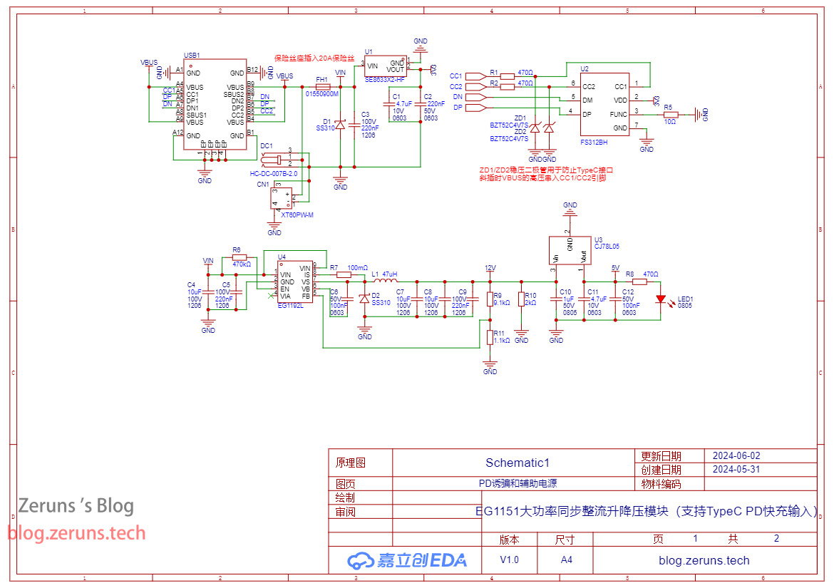
The PD3.1 spoofing chip used is the FS312BH, which can spoof a PD charger to output up to 48V. If the charger does not support this voltage, it will automatically select the closest voltage. For example, if your PD charger supports a maximum of 28V, it will output 28V. (As of the time of writing, it seems that most PD3.1 chargers on the market can only output up to 28V.)
To require a 28V Type-C input, besides the charger supporting PD3.1 28V, your data cable also needs to have an E-mark chip and support the PD3.1 ERP28V protocol.
Note: The three input interfaces cannot be used simultaneously; they are connected in parallel!
Video demonstration: https://www.bilibili.com/video/BV1fS411P7Cp/
Download link at the end of the article!
This module is designed for a maximum current of 20A, but in actual testing, it only reaches about 18A. At 18A, the voltage drop is already quite noticeable!
It's not great, so please don't criticize too harshly. If you have any suggestions for improvement, please leave them in the comments section. Friendly discussion is welcome.
Electronics/Microcontroller Technology Exchange QQ Group: 820537762
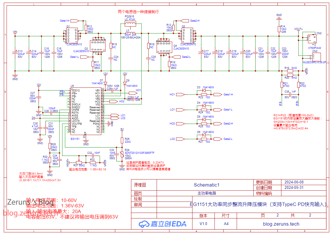
EG1151 Introduction:
The EG1151 is a four-switch buck-boost DC-DC power management chip. It integrates a reference power supply, oscillator, error amplifier, current limiting protection, short-circuit protection, half-bridge drive, and other functions. It can adopt corresponding control strategies based on the specific relationship between input and output voltages and different load conditions. It provides a stable voltage output across the entire fluctuation range of the input voltage. It is very suitable for applications requiring wide voltage range and high current boost/buck conversion, especially in situations where battery power voltage is not constant, and it also supports battery charging.
Features:
Wide input voltage range: 7V-150V;
High efficiency, up to 95%;
Undervoltage protection;
Over-temperature protection
; Supports battery charging;
Output short-circuit protection.
Package type: QFN32.
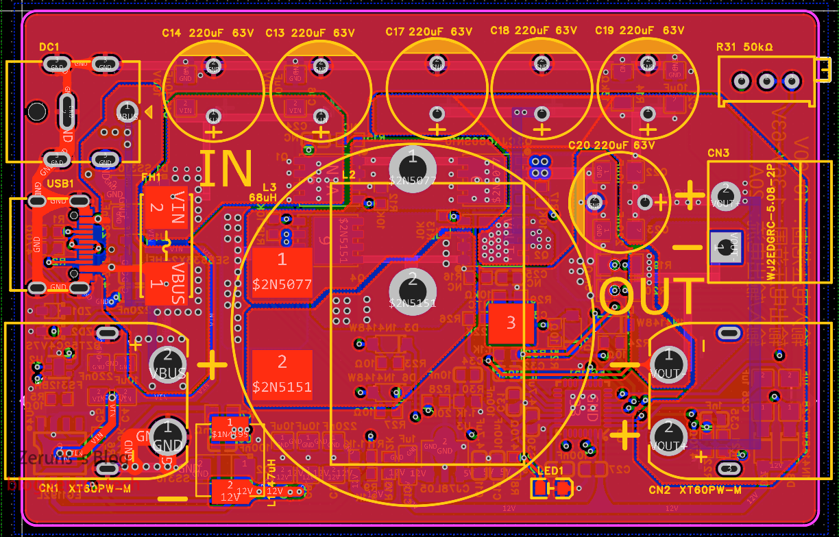
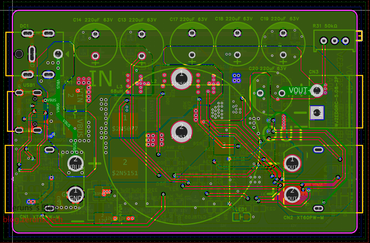
The actual product image


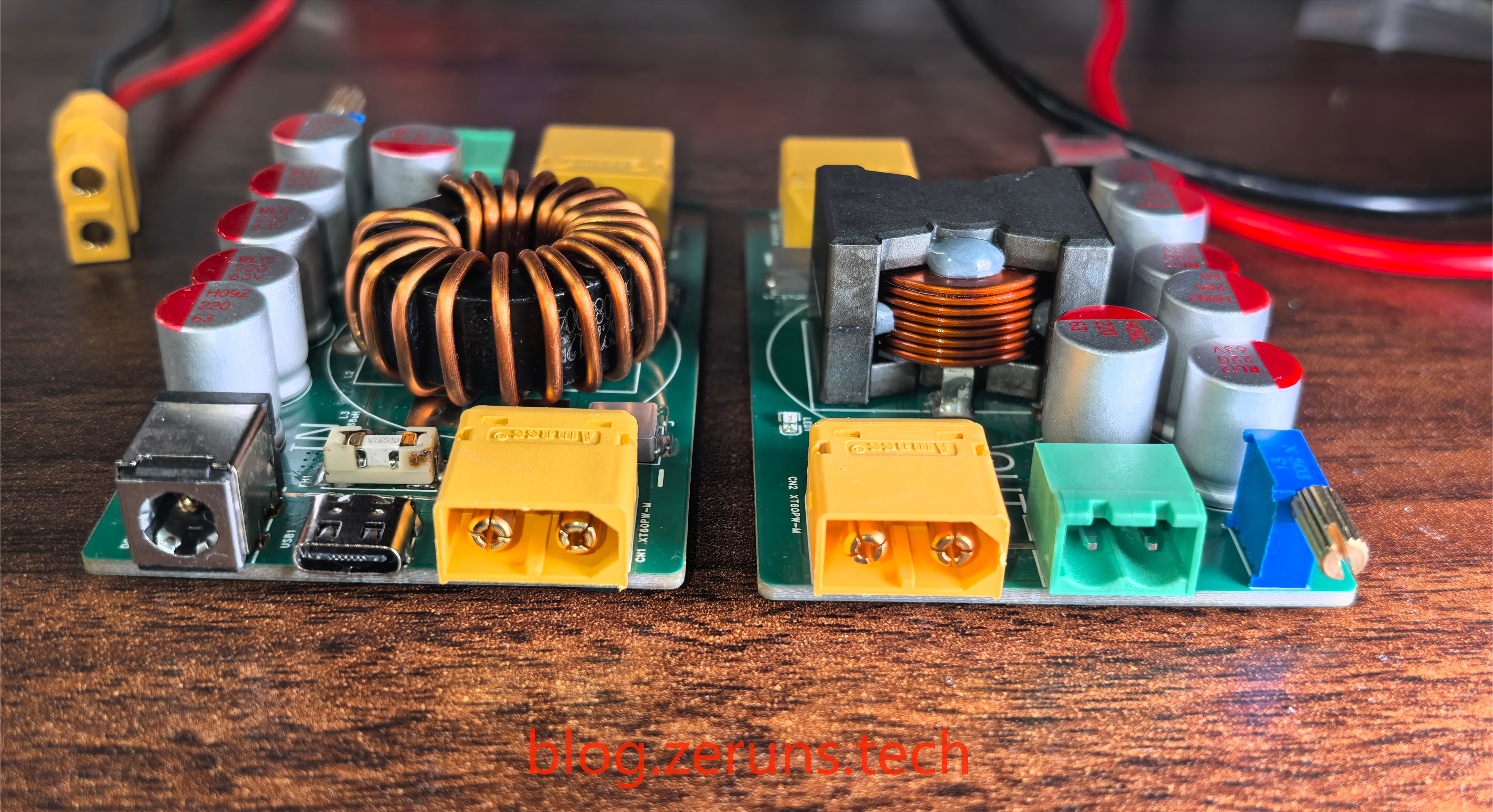
shows an aluminum shell purchased from Taobao, while the front and back covers were designed and 3D printed. 3D models of the shell and front/back covers are also included in the documentation. Regarding


chip soldering techniques:
The EG1151 chip is in a QFN32 package, and the FS312BH chip is in a DFN2X2-6L package. Both packages are very small and relatively difficult to solder, requiring some skill.
When soldering these two packages, if your PCB uses immersion gold plating, first apply solder to the pads; if it uses tin plating, apply solder to the chip pins. Note that it's best to use medium-low temperature solder (high temperature solder is difficult to use). Don't apply too much solder to the middle pads; just a little is enough, otherwise it will push the chip up and prevent the pins around it from making contact. If too much solder is applied, clean the soldering iron and slowly remove the solder, or use desoldering wick. After applying the solder, squeeze a little solder flux onto the pads, place the chip on them, and then place it on a heating plate or use a hot air gun. After the solder melts, gently move the chip with tweezers. If it automatically returns to its original position, it's done. After it cools down, check for any solder bridges. If there are any, repair them with a soldering iron.


Testing was performed
using an XT60 interface with a 24V input. The XT60 output interface was connected to a multimeter and an electronic load.

Using a Type-C input, a Cooltech 140W PD3.1 charger was connected, and it successfully induced 28V.

The maximum output is 63V.

Test equipment used:
HP 34401A 6.5-digit multimeter: https://blog.zeruns.tech/archives/772.html;
Ryton RD6012P digitally controlled adjustable power supply: https://blog.zeruns.tech/archives/740.html
; RIGOL DHO914S oscilloscope: https://blog.zeruns.tech/archives/764.html
; Juwei Electronics load: https://s.click.taobao.com/EdLEpkt. The highest efficiency obtained in the
conversion efficiency test was 96.869%. The test data is shown in the table below: Input Voltage (V) Input Current (A) Input Power ( W) Output Voltage (V) Output Current (A) Output Power (W) Conversion Efficiency (%) 36.000 6.932 249.552 48.194 4.996 240.777 96.484 60.000 6.264 375.840 35.669 9.995 356.512 94.857 48.000 9.434 452.832 28.841 14.993 432.413 95.491 60.000 5.941 356.460 18.430 17.988 331.519 93.003 60.000 4.270 256.200 12.129 18.990 230.330 89.902 12.001 10.913 130.967 24.003 5.002 120.063 91.674 25.000 9.915 247.875 23.749
10.008
237.680
95.887
12.004
9.889
118.708
36.068
3.002
108.276
91.213
12.004
2.291
27.501
5.070
5.000
25.350
92.178
12.004
9.130
109.597
10.116
10.013
101.292
92.422
48.000 7.812
374.976
36.188
10.005
362.061
96.556
48.000
8.658
415.584
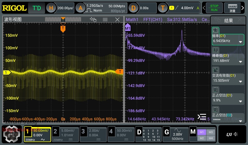
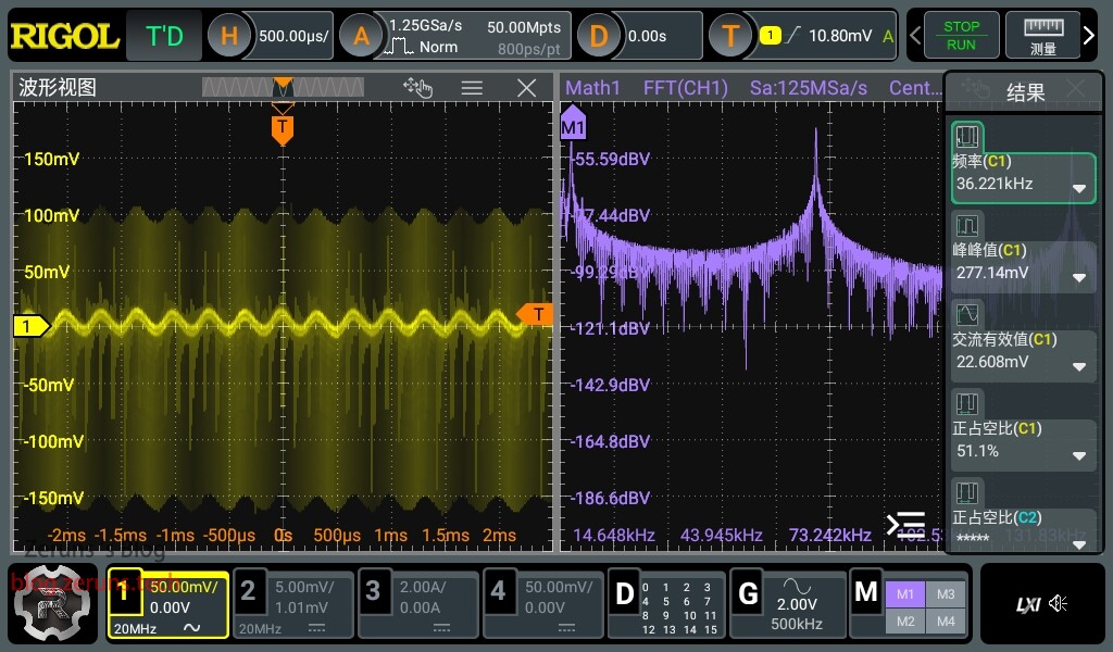
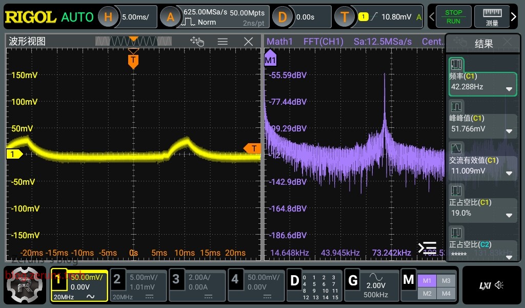
50.315 8.001 402.570 96.869 Ripple Test : The peak -to-peak ripple value for a 12V no-load output is approximately 32mV; the peak-to- peak ripple value for a 12V 10A no-load output is approximately 191mV; the peak-to-peak ripple value for a 12V 15A output is approximately 277mV; the peak -to-peak ripple value for a 36V no-load output is approximately 51mV; the peak-to-peak ripple value for a 36V 3A output is approximately 292mV; the peak-to-peak ripple value for a 60V no-load output is approximately 114mV; the peak-to-peak ripple value for a 60V 3A output is approximately 32mV. Schematic Diagram : Main Power Circuit; PD Decoy and Auxiliary Power Supply Circuit; PCB Top Layer; Inner Layer 1; Inner Layer 2; Bottom Layer; Component Purchase Addresses: Most of the components used in this project can be purchased here: 0603 Resistor and Capacitor Sample: https://s.click.taobao.com/SXT7pkt Type-C female connector 16P: https://s.click.taobao.com/vjLRskt EG1151 chip: https://s.click.taobao.com/le3gAkt EG1192L chip: https://s.click.taobao.com/pG2gAkt CJAC80SN10 MOSFET: https://s.click.taobao.com/aPsWWlt XT60PW interface: https://s.click.taobao.com/6jZ7pkt It is recommended to purchase components from LCSC's online store: https://activity.szlcsc.com/invite/D03E5B9CEAAE70A4.html Click on the BOM in the LCSC open-source link to immediately place an order on LCSC's online store; you can import the required components into your shopping cart with one click. Download links below include: LCSC EDA project, schematic PDF file, datasheets for various chips used, and 3D model files of the casing. Baidu Cloud download link: https://pan.baidu.com/s/1gNl48K25p6Pr3gi9lsyMAg?pwd=tmsv Extraction code: tmsv 123 Cloud download link: https://www.123pan.com/s/2Y9Djv-r3tvH.html Extraction code: 0cGK If you find this useful, you can tip me through the 123 Cloud links above. If it's a WeChat article (WeChat Official Account: zeruns-gzh), you can also click "Like Author" at the bottom of the article to tip me. Thank you. Other recommended open-source projects include: a three-phase power consumption data logger for easy monitoring of home electricity usage (https://blog.zeruns.tech/archives/771.html); an STM32F407-based LVGL project template (MSP3526 screen), including FreeRTOS and bare-metal versions (https://blog.zeruns.tech/archives/788.html); an STM32-based synchronous rectification Buck-Boost digital power supply (https://blog.zeruns.tech/archives/791.html); and the LM25118 automatic buck-boost adjustable DC-DC power module (https://blog.zeruns.tech/archives/727.html). EG1164 high-power synchronous rectification boost module open source, with a maximum efficiency of 97%: https://blog.zeruns.tech/archives/730.html 4G environmental monitoring node based on Zeruns Air700E (data on temperature, humidity, air pressure, etc.), uploading data to Alibaba Cloud IoT platform via MQTT: https://blog.zeruns.tech/archives/747.html Smart electronic load based on CH32V307 open source, an embedded competition entry open source: https://blog.zeruns.tech/archives/785.html


 京公网安备 11010802033920号

 HX6356PVRC


