Please note that this project is for personal learning and sharing purposes only. It is not recommended to adopt this solution to reduce costs. This solution has not undergone professional verification and inspection. I do not have the datasheet and official design schematic for the RTL8156 chip, and there may be several unknown issues and faults. Stability needs further consideration. Compared to products with the same chip currently on the market, this project is neither cheap (costing approximately 35 RMB) nor stable, and there is no after-sales service. Please weigh the pros and cons carefully before DIYing solely for the sake of "cheapness." Thank you!
Updated 2024.6.7: Please read Part Twelve.
Project discussion group (QQ): 753341673
I. Acknowledgements
This project references and modifies existing projects:
https://oshwhub.com/aknice/rtl8153b
(referencing the USB Type-C switching part of this project)
https://oshwhub.com/vvwall/tao_net
(referencing the 2.5G Ethernet part of this project).
Thanks to the two contributors for their open-source contributions, which made this project possible!


II. Project Status:
Some functions of this project have been verified and can be built directly, but there will be some problems.
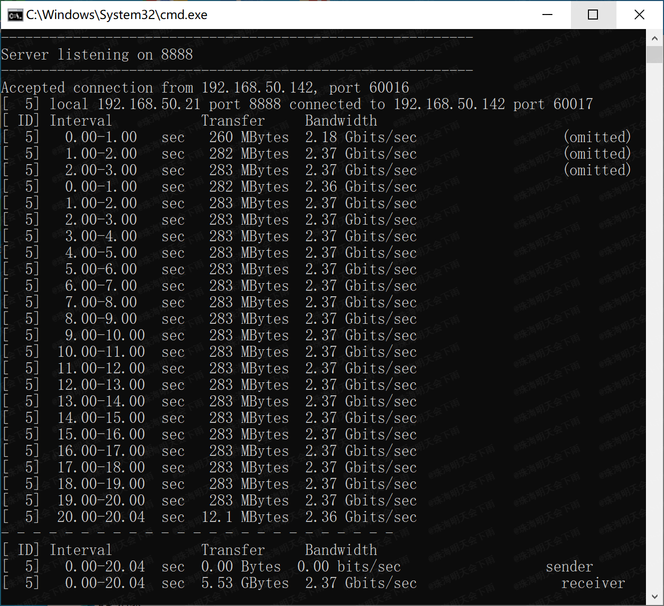
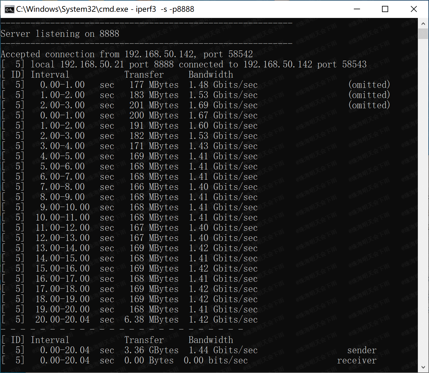
Currently, the network card's receiving speed is basically up to 2.37Gbps,
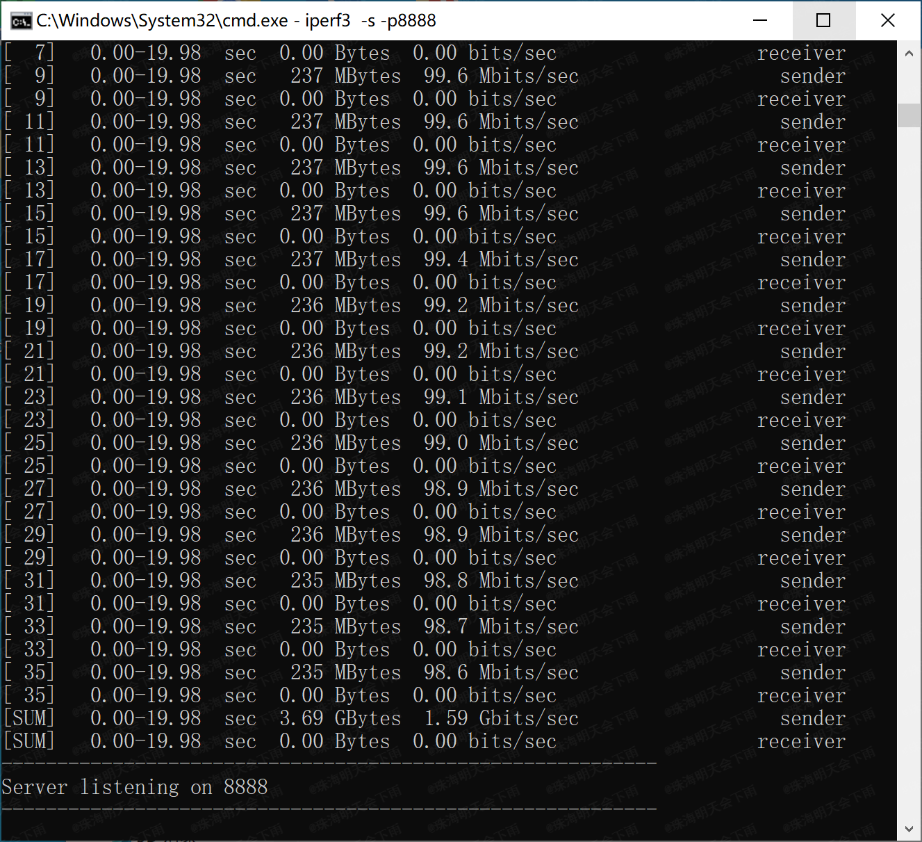
but the sending speed has issues, only reaching 1.44Gbps (resolved).
Test environment: Two computers, both running Windows 10, one a 2016 Mac using the network card from this project, and the other an ASUS B550 5800X combination using the onboard Intel I225-V network card.
Throughput testing was performed using iPerf3
(updated 2024.6.7).
After driver correction,
the network card's receiving and
sending commands were tested.
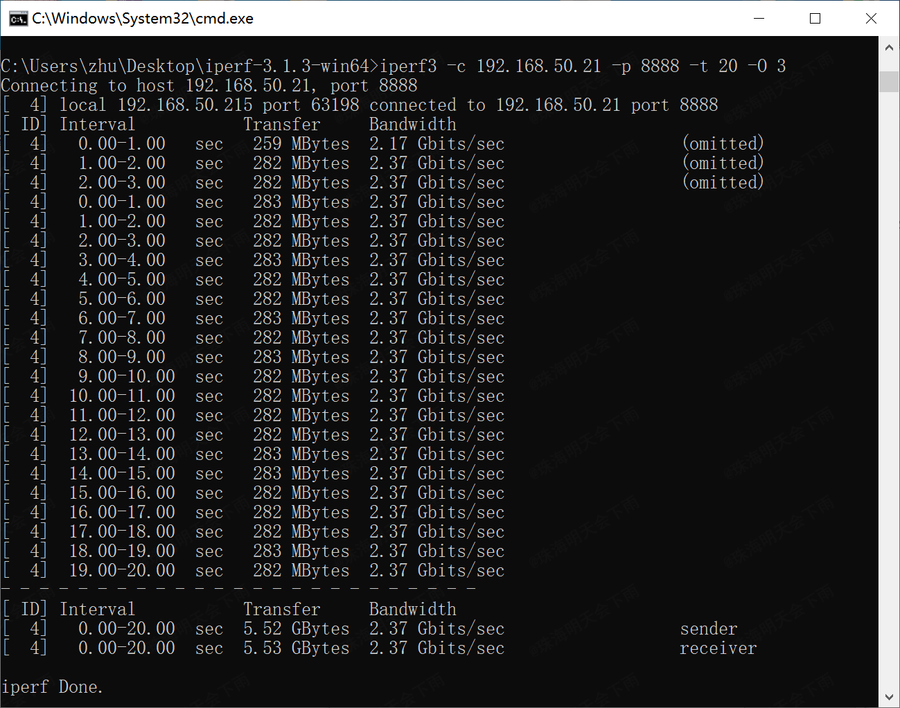
The network card's receiving
command was: `iperf3 -c 192.168.50.21 -p 8888 -t 20 -O 3` (all commands were entered on the ASUS machine; the network card in this project acts as the server).
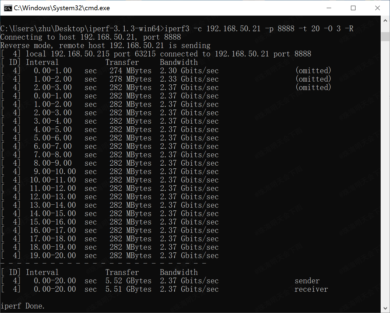
The network card's sending
command was: `iperf3 -c 192.168.50.21 -p 8888 -t 20 -O 3`. -R
for multi-threaded receive, command: iperf3 -c 192.168.50.21 -p 8888 -t 20 -O 3 -P 16
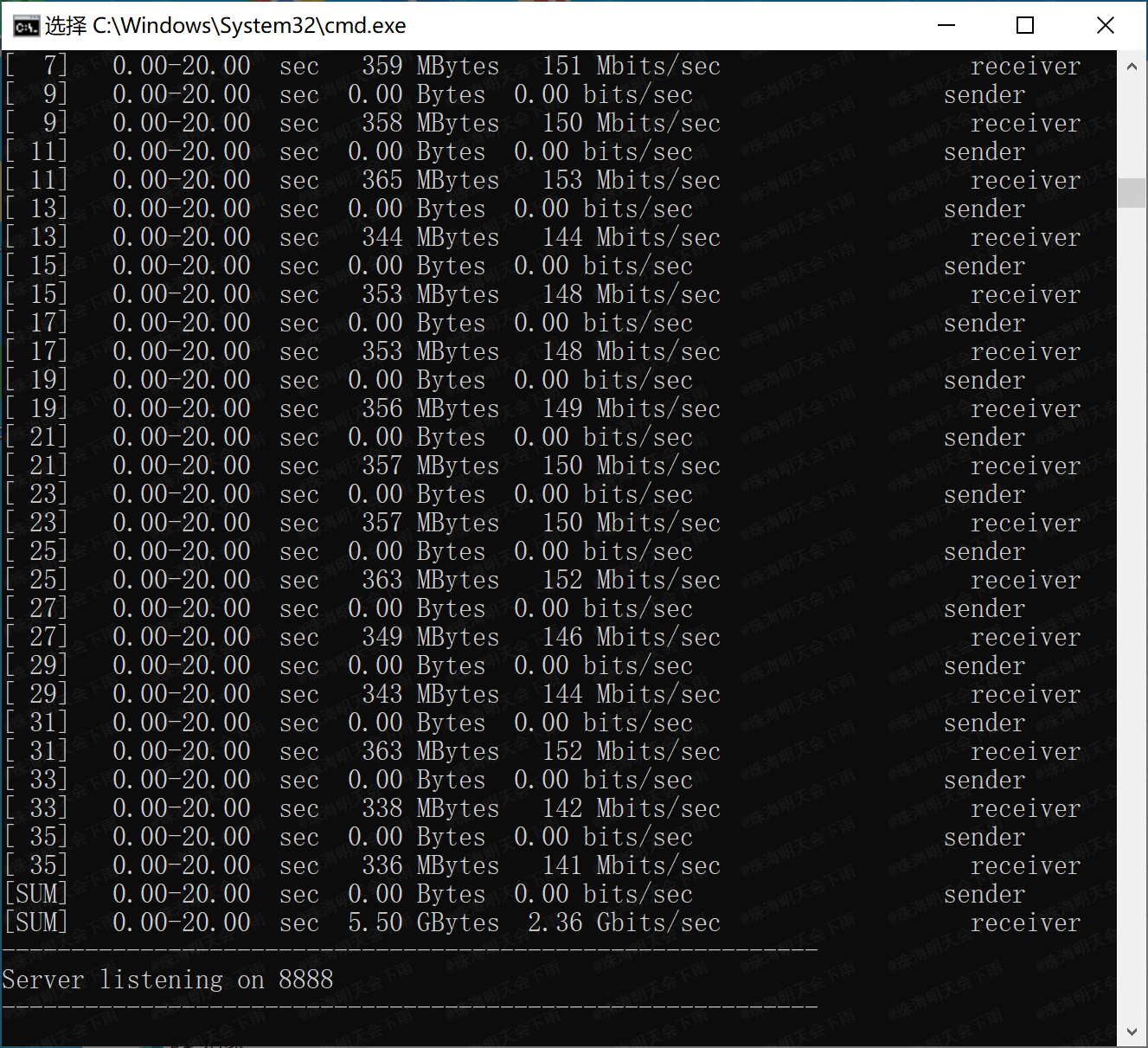
Multi-threaded send, command: iperf3 -c 192.168.50.21 -p 8888 -t 20 -O 3 -R -P 16
The currently suspected causes of the fault are as follows (resolved):
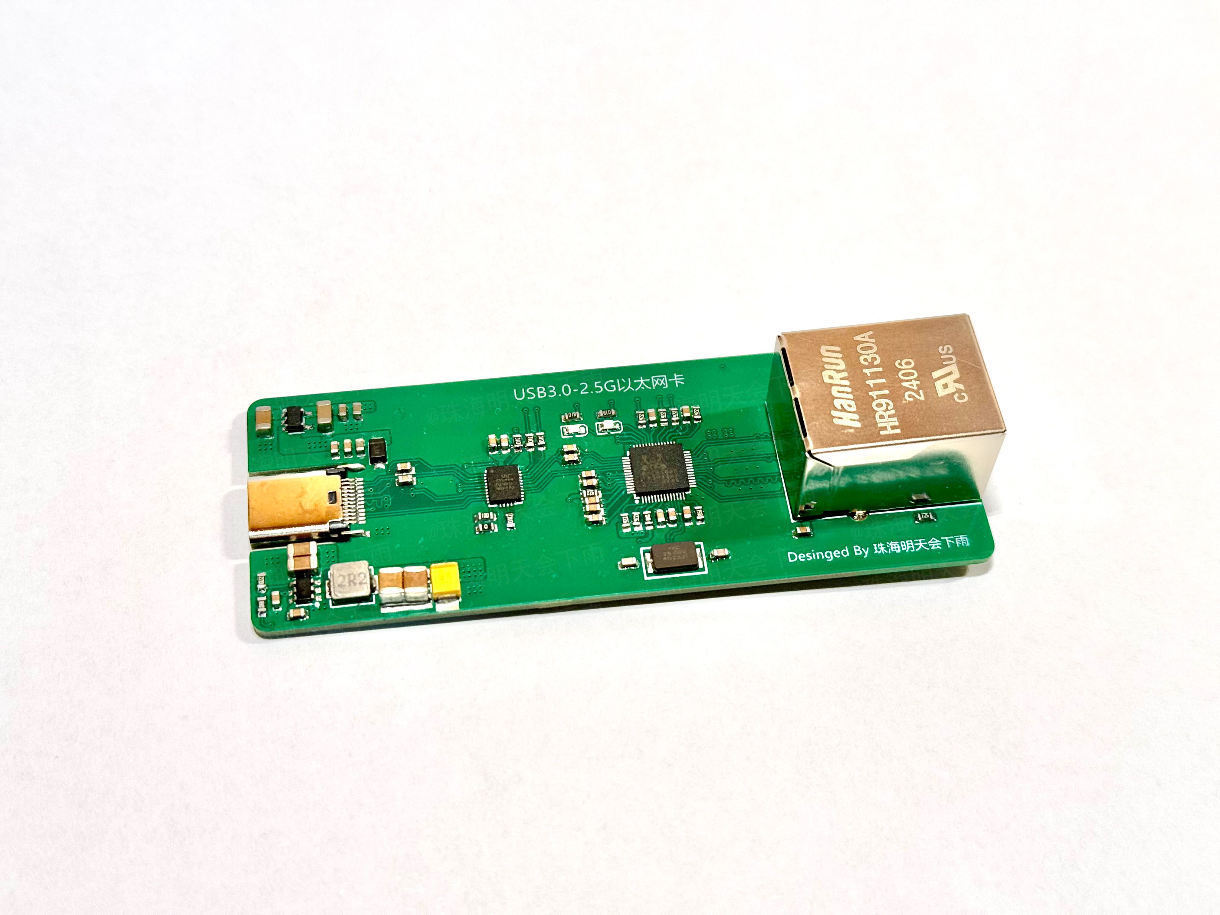
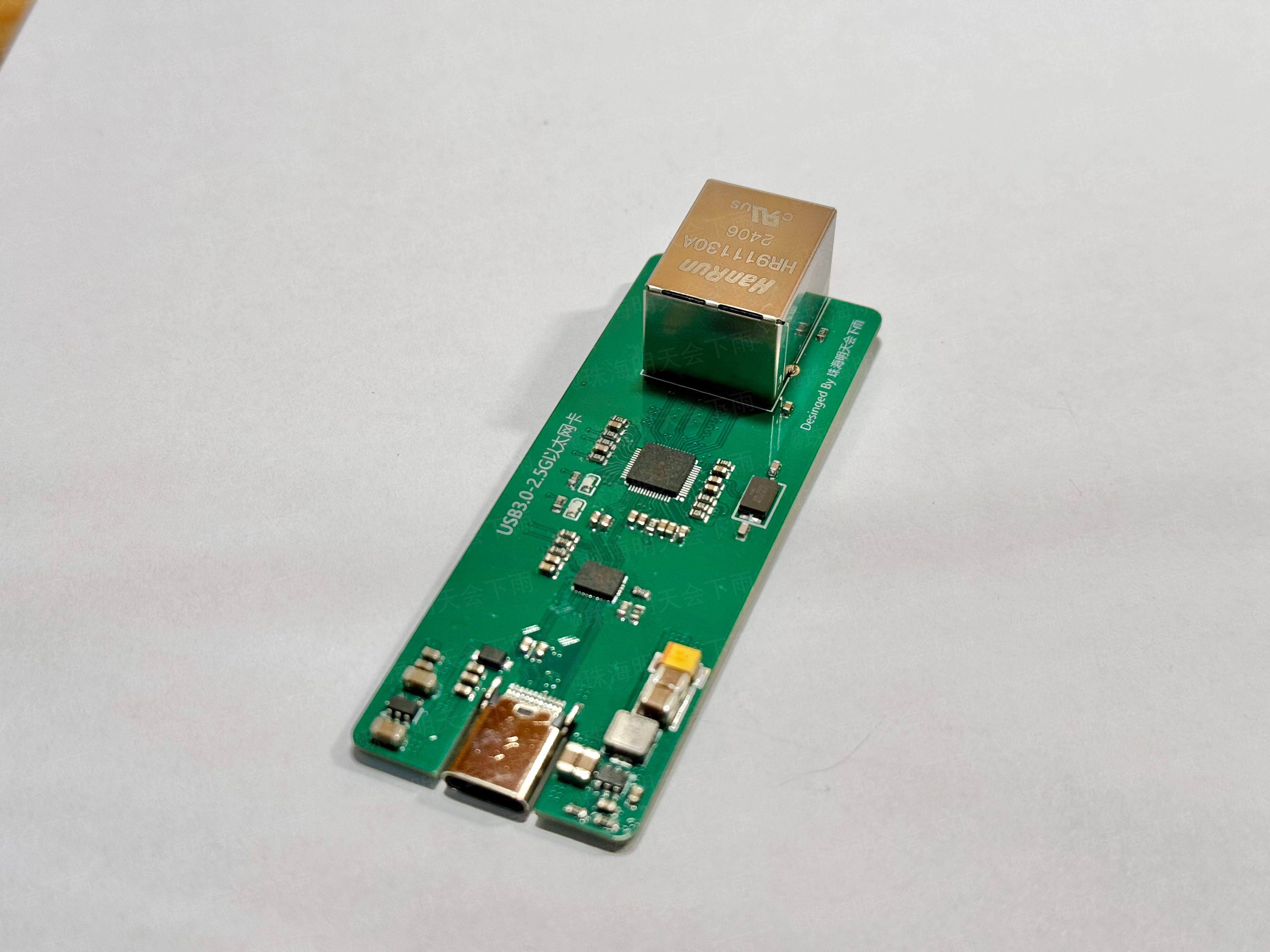
1. For convenience, this project used an integrated network interface transformer component (HR911130A) that could only operate at 1Gbps speed.
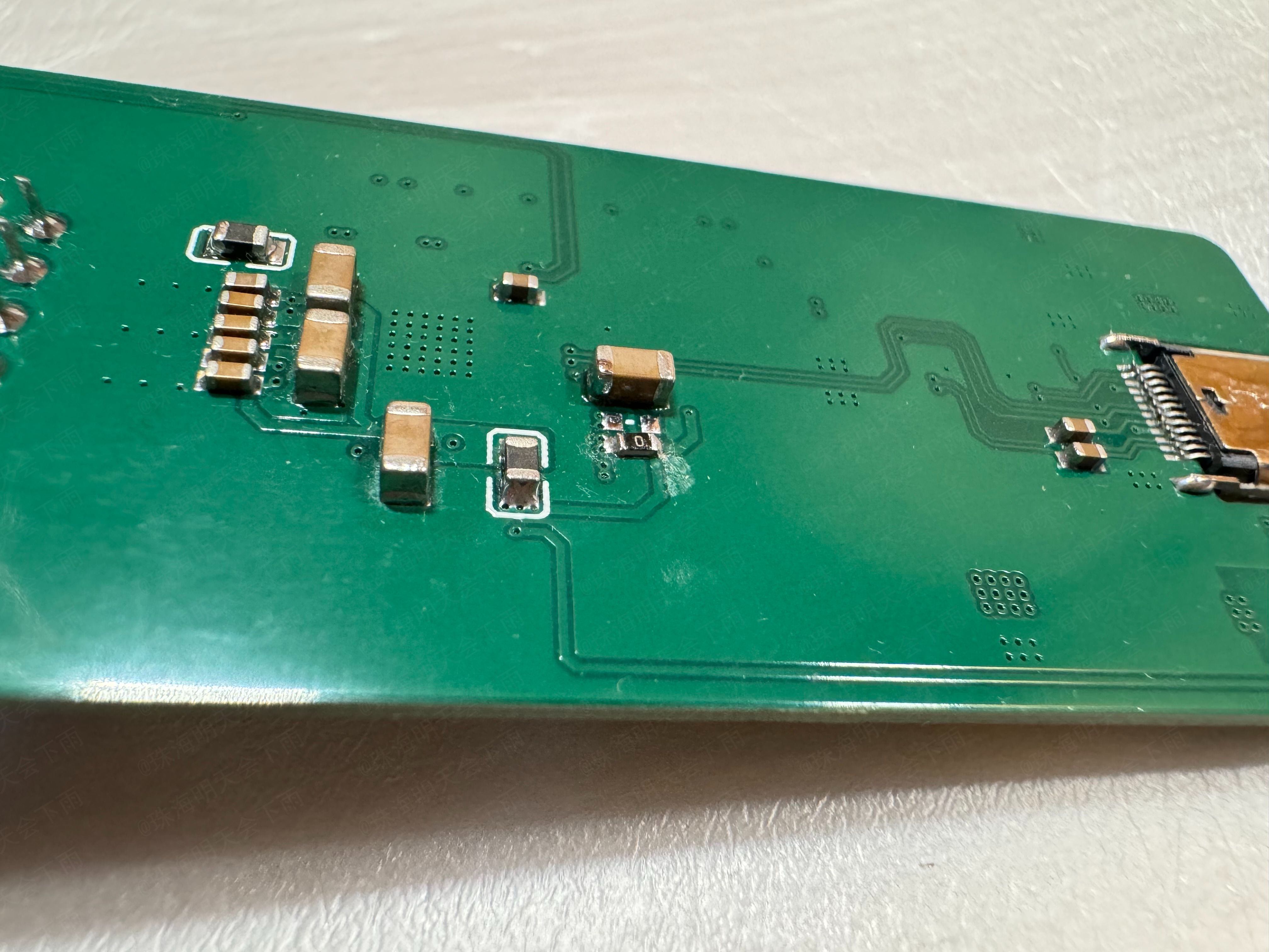
2. For ease of soldering, the USB 3.0 circuitry in this project used coupling capacitors with a 0603 package size
. 3. There may be unknown issues with the wiring.
III. Operating temperature:
After a continuous 1-minute receive/transmit test, the surface of each chip and the front and back surfaces of the PCB felt warm. At
a room temperature of 22.3 degrees Celsius
, iPerf3 was used to send multi-threaded stress test
commands: `iperf3 -c 192.168.50.21 -p 8888 -t 20 -O 3 -R -P 32`.
The infrared temperature recorded on the front (chip side) around the 50th second of the stress test was 40.1 degrees Celsius.

The infrared temperature recorded on the back (around the 54th second of the stress test) was 37.8 degrees Celsius.

IV. Impedance Matching:
The 4-layer board with a stack-up structure of JLC process, JLC04101H-3133 (1.0mm board thickness),
is calculated using the official JLC impedance calculator as follows: (https://tools.jlc.com/jlcTools/index.html#/impedanceCalculatenew)
For the USB 2.0 section, a differential impedance of 90 ohms is used, resulting in a line width of 6.2mil and a spacing of 8mil.
For the USB 3.0 section, a differential impedance of 95 ohms is used, resulting in a line width of 5.5mil and a spacing of 8mil.
For the MDI section, a differential impedance of 100 ohms is used, resulting in a line width of 5.2mil and a spacing of 10mil
. V. Schematic Diagram:

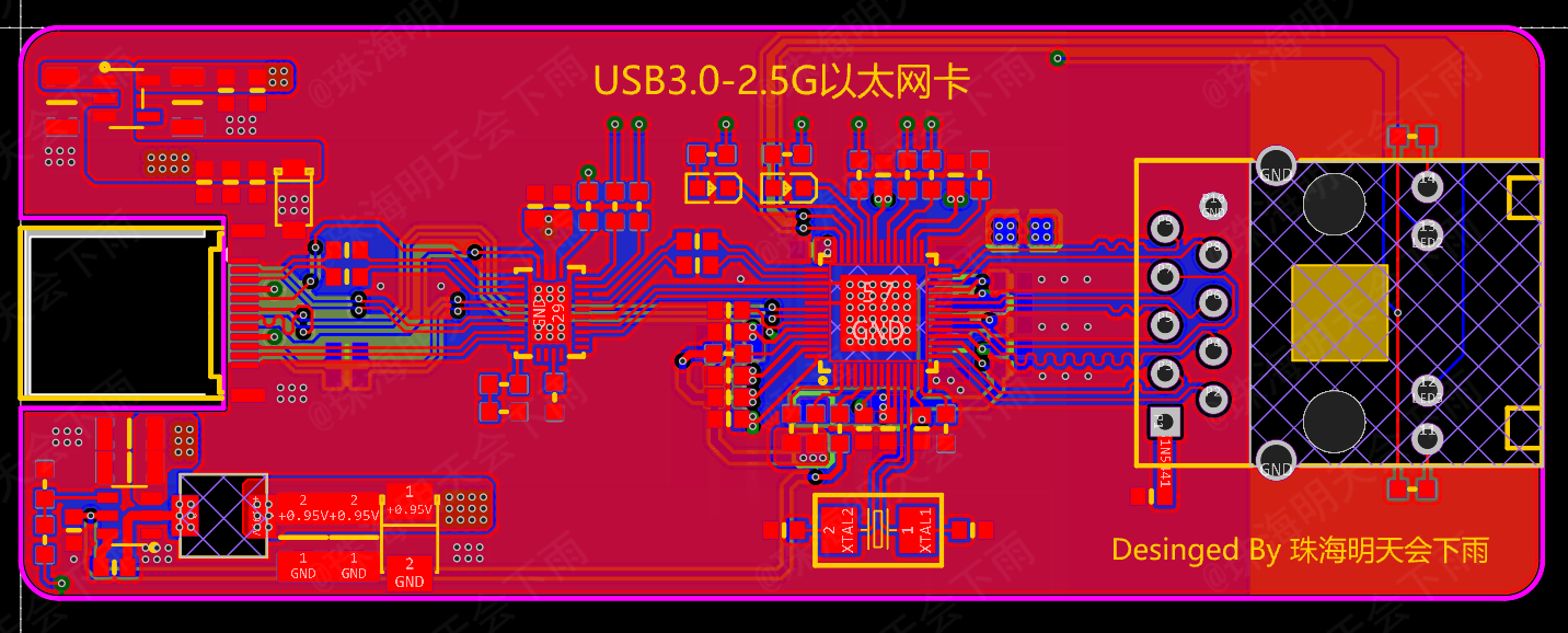
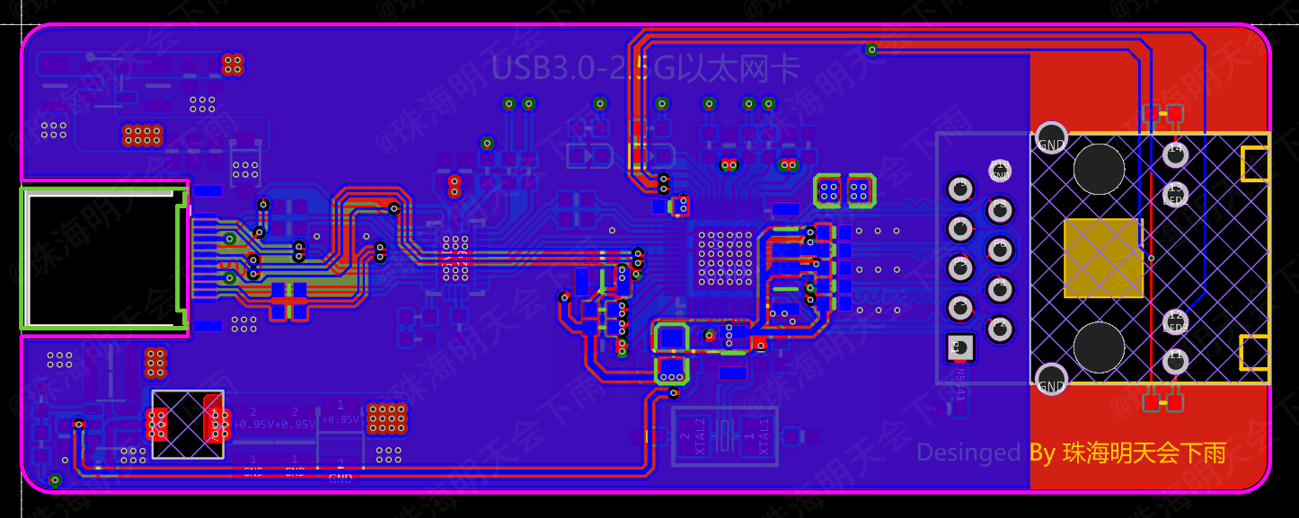
VI. PCB Diagram:
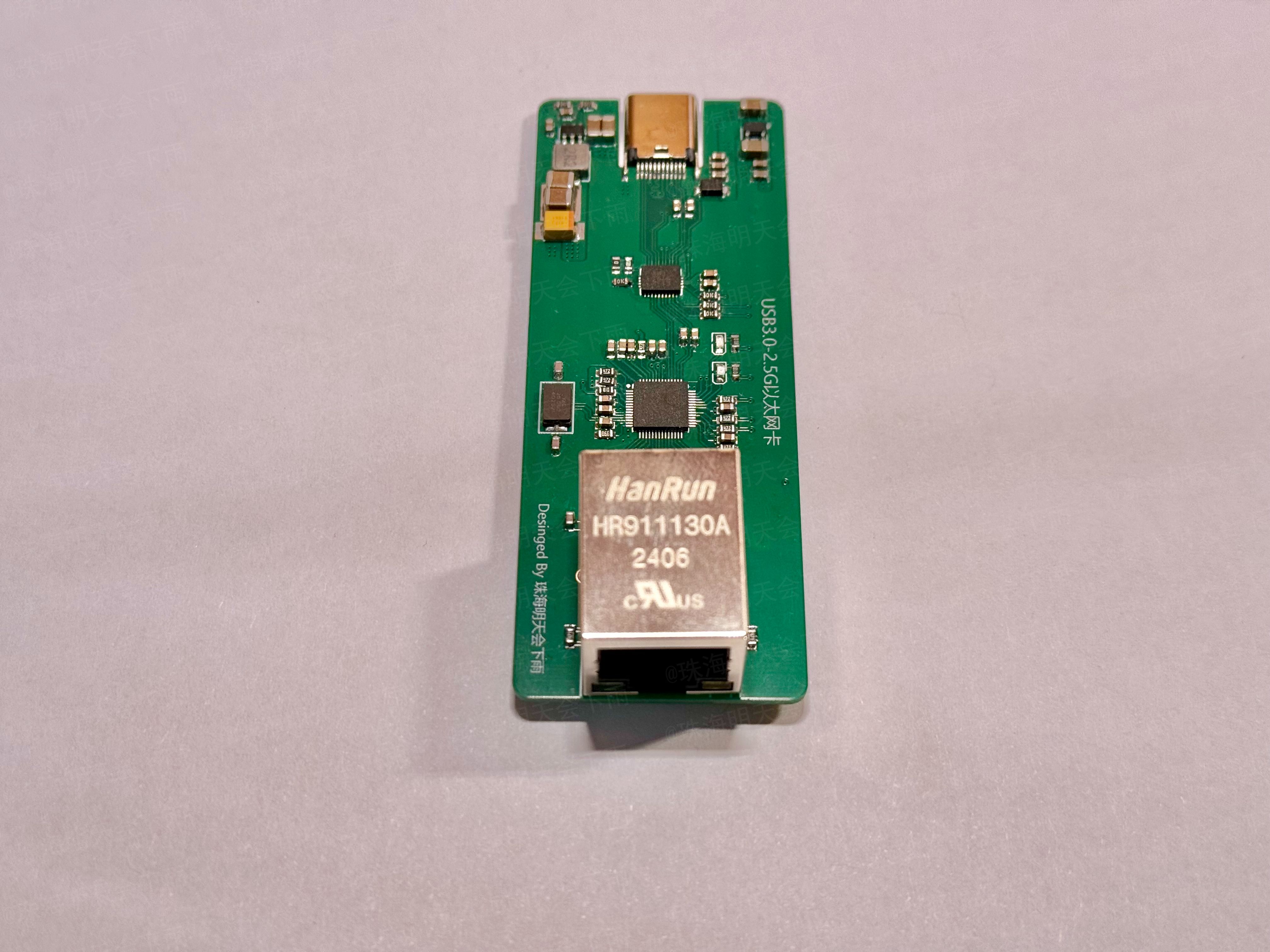
Top Surface,
Inner Layer 1,

Inner Layer 2,

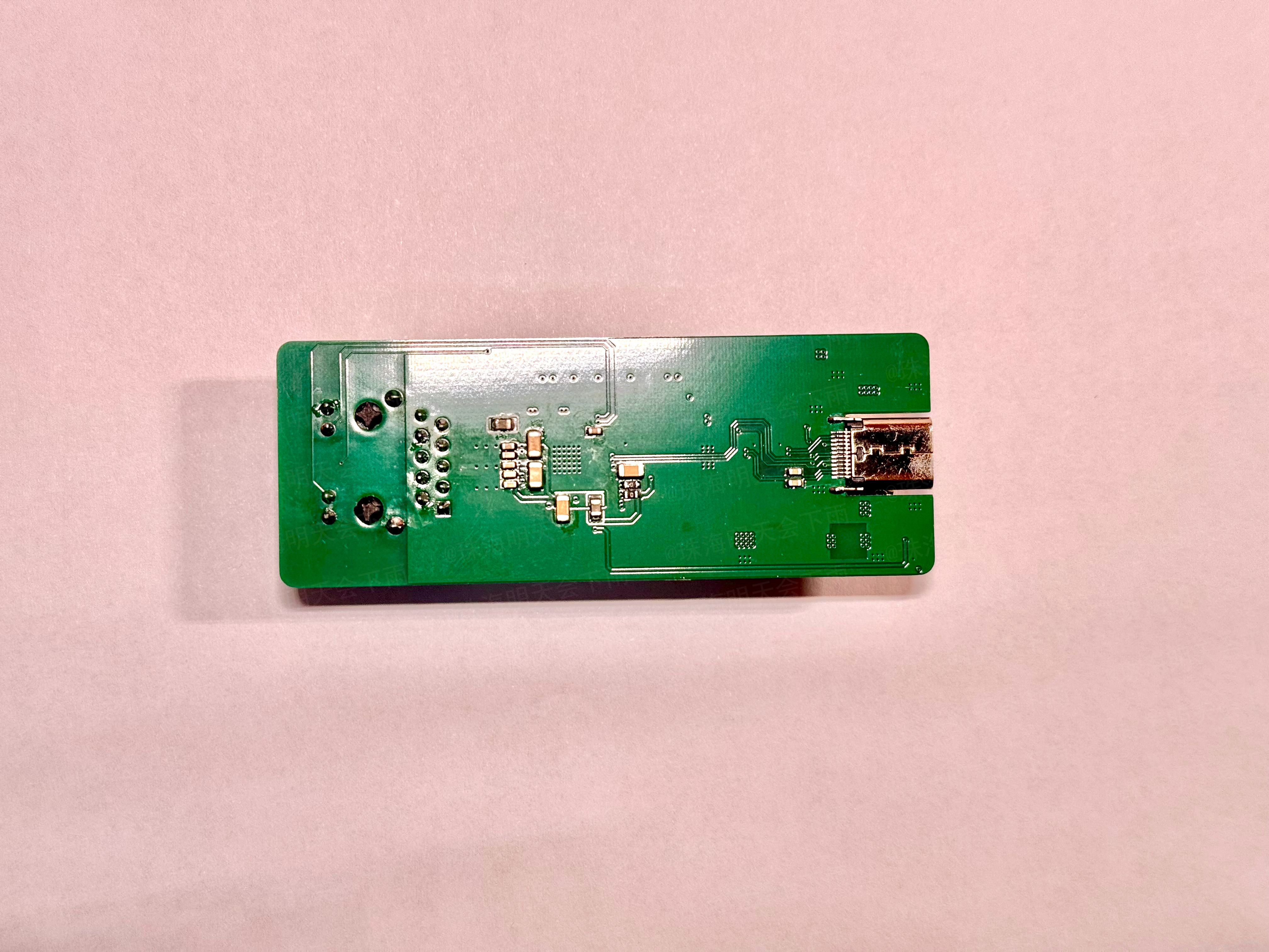
Bottom Surface
VII. Power Supply Diagram: VIII.

Partial Component Price Reference:
RTL8156B-CG 25 RMB
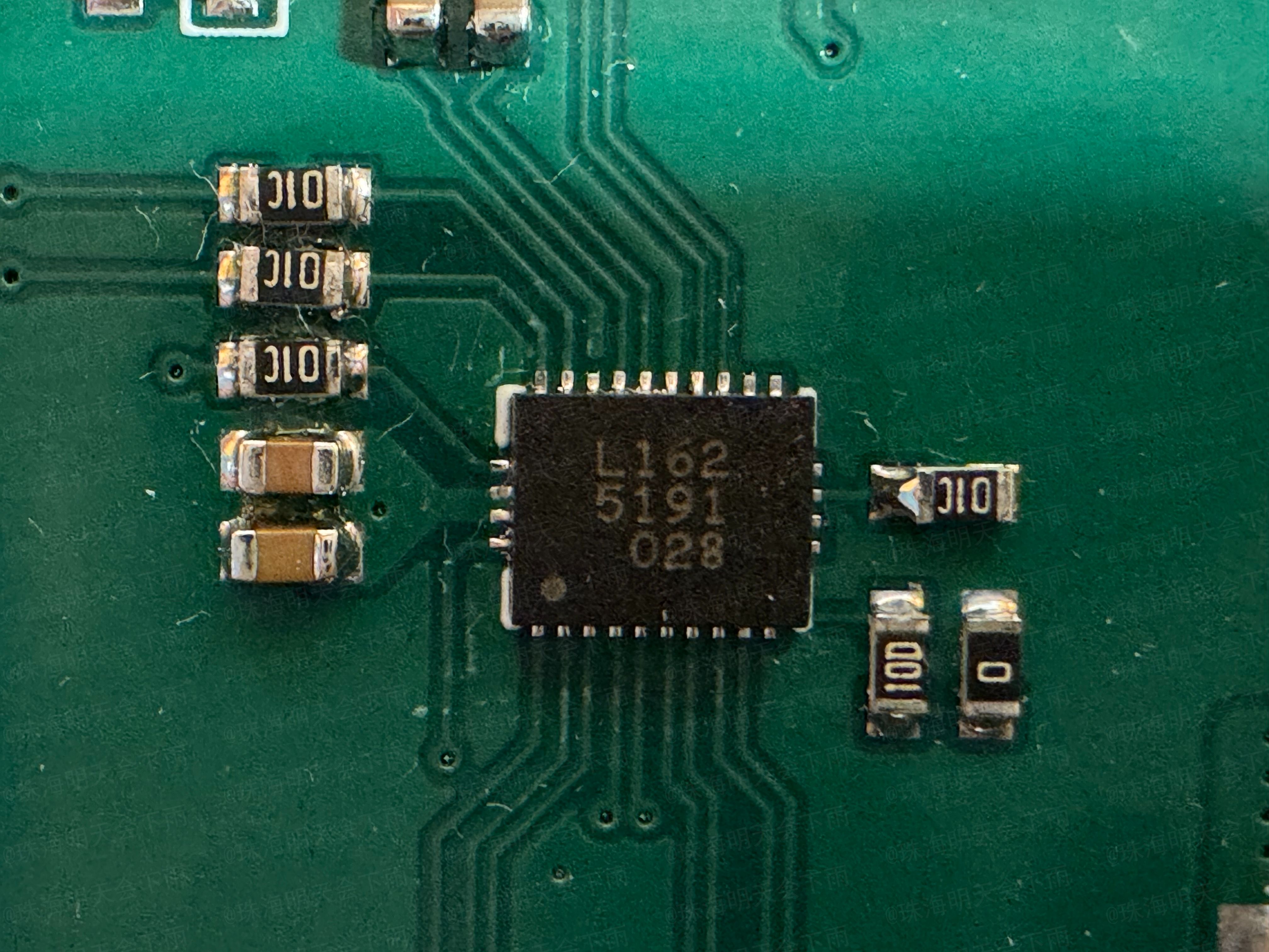
, VL162 3 RMB,
HR911130A 5 RMB (possibly counterfeit),
Used USB Type-C SuperSpeed Data Cable 16 RMB
IX. Partial Design Reference:
VL160: https://www.via-labs.com/product_show.php?id=72
VL162: https://www.via-labs.com/product_show.php?id=106
VL162 Reference: https://blog.csdn.net/weixin_54493972/article/details/119379313
X. Production Suggestions:
Please do not use the BOM automatically generated by the JLC system or directly perform SMT, as they are inaccurate. Please refer to the attribute values in the project file. I have also uploaded my own BOM for reference (it may contain errors, please double-check).
The design documents for this project are suitable for 4-layer boards using JLC technology, with a stack-up structure of JLC04101H-3133 (1.0mm board thickness), and impedance control within 20%.
The USB-C female connector can only be installed on PCBs with a board thickness of 1.0mm or less.
The tantalum capacitor in the output capacitor that steps down to +0.95V is optional.
All capacitors except tantalum capacitors must be installed, and the capacitance of the 1206 capacitors cannot be too small.
When soldering QFN chips, place a small amount of solder (about the size of a grain of rice) on the center GND side, and use slightly more solder around the edges to ensure the solder wets the chip leads. After mounting the chip on the front, use a heated soldering station. Finally, use a soldering iron and flux to remove excess solder around the edges.
Please note that QFN chips are very prone to cold solder joints; it is recommended that inexperienced users practice soldering using other scrapped chips first.
After completing the front-side component placement, use a bracket to flip the PCB board and continue with the back-side component placement. Back-side soldering should be done using a hot air gun. For integrated hot air guns, select 360 degrees and 30% airflow, preheat first, then target specific areas for soldering.
Please note that when soldering the back side, do not allow front-side components to touch other objects and shift.
After soldering, clean the flux using a reputable brand-name cleaning agent. A relatively large amount may be needed. Except for plastic parts such as connectors, you can directly soak the components in the cleaning agent for cleaning. After cleaning, actively wipe the cleaning agent dry with a paper towel or lint-free cloth; do not wait for it to evaporate on its own to avoid residue.
XI. Future Outlook
: Adding ESD/TVS protection devices to the USB interface accessories
; optimizing cabling;
and replacing the wiring with RJ45 connectors and network transformers compliant with 2.5G and above standards.
XII. Subsequent Updates
(June 7, 2024):
1. The issue of the network card's transmission speed not meeting the standard has been successfully identified. The main cause was a problem with the Windows network card driver on the test computer. For details, please see https://www.acwifi.net/21188.html and https://www.bilibili.com/video/BV1pS4y1p7qS. The above two web pages and videos basically confirmed that it was a network card issue. After correcting the driver to version 10.54.608.2022, the transmission speed returned to normal. The driver has been uploaded as an attachment. Please note that this driver is from the internet and may contain viruses or other risks. If possible, please obtain it from the Realtek official website. After the repair, the transmission speed can be maintained at 2.37G. Specific speed test images have been updated above.
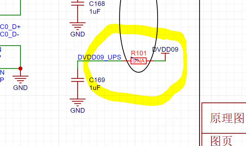
2. Thanks to @Filter_Capacitor for the suggestion. The point that "the manual clearly emphasizes that chip Pin54 should not be connected to other 0.95V power supplies" has been verified; it runs normally and passes stress testing. Simply leave R101 empty (remove it, do not attach it) to disconnect Pin54 from other 0.95V power networks. There were instances of transmission rate fluctuations when R101 was not disconnected, but removing it resolved the issue.

3. Issues regarding coupling capacitors and wiring will be updated in later versions. Since I haven't received the datasheet yet and am unsure of the LED configuration, I'm temporarily putting the new version on hold. I will create a second version once all issues are resolved.
Note:
This is my first official open-source project, and there may be many shortcomings. Criticism and corrections are welcome. I will actively revise and respond when I have time. Thank you!
Please do not use this project directly for commercial purposes!
The content, including the project description text, may not be directly copied and used for commercial purposes!
Postscript:
Please note that safety is paramount. There are safety risks involved in the construction of this project. Gases generated during soldering and cleaning may pose a threat to your health. Please wear appropriate protective gear before proceeding; a mask capable of filtering harmful gases is essential.
Since this project involves two QFN packaged components, soldering techniques are required. Please be careful during soldering. After soldering, thoroughly clean the flux and other substances around the chips. Carefully inspect the soldering of each pin under light to ensure there are no unsoldered areas or bridging.
Furthermore, due to the large number of pins on the USB Type-C interface, it is recommended to build or purchase a test card to check the connections of each pin.
Regarding the reason why the USB-C interface uses a MUX chip for switching instead of a direct connection, this is primarily a requirement of the USB-IF Association (not really), mainly for signal integrity. For details, please refer to this article from Texas Instruments (TI). This project (https://www.ti.com.cn/cn/lit/wp/zhcy153a/zhcy153a.pdf?ts=1714722629686
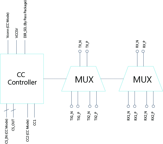
) only performs the most basic impedance matching; there is still room for improvement in power supply and signal layout.
Furthermore, since the official datasheets for the VL160/VL162 and RTL8156 chips used in this project seem to be kept confidential, this project may carry certain legal risks.
Finally, happy learning/project!


 京公网安备 11010802033920号

 1CS245-01GG


