 Application environment limitations:
  —————————————————————————Supercapacitor and Balancing Circuit————————————————————————————————
  ① Fast charging speed: over 95% of rated capacity can be reached in 10 seconds to 10 minutes;
  (2) Why do supercapacitors need balancing capacitors?
  Characteristic Curves:
 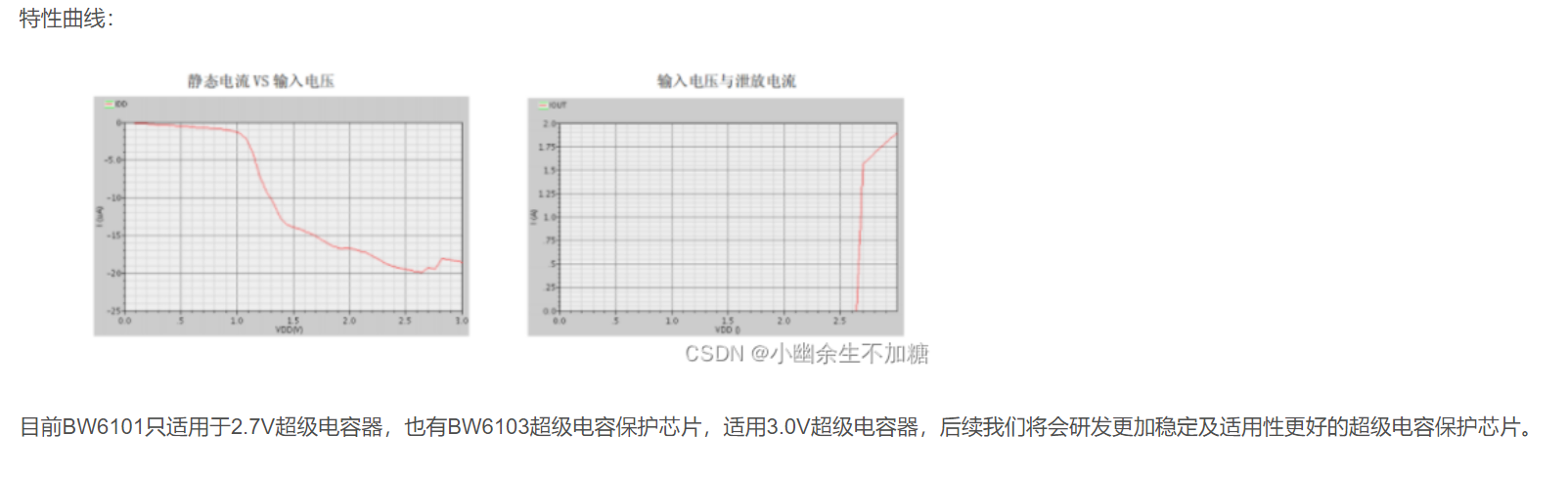 ————————————————————————RM Supercapacitor Roundtable Forum——————————————————————————
  ② The voltage fluctuation within the cycle is large, and the discharge is unbalanced, requiring the use of a DC-DC circuit.
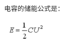
 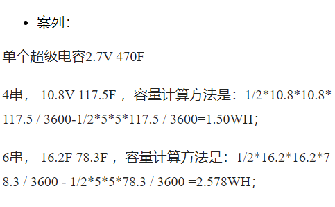 Formula for energy release from a capacitor: ⑥ Formula for energy storage in a capacitor:
 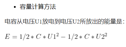 ——
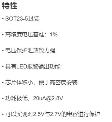
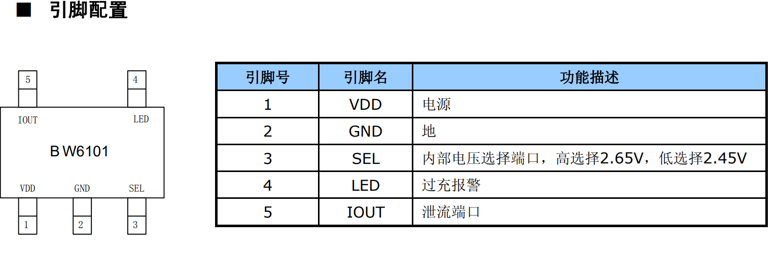
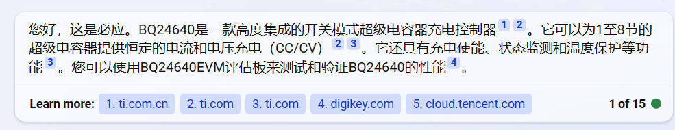
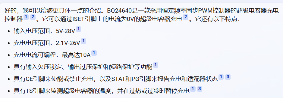
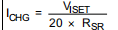
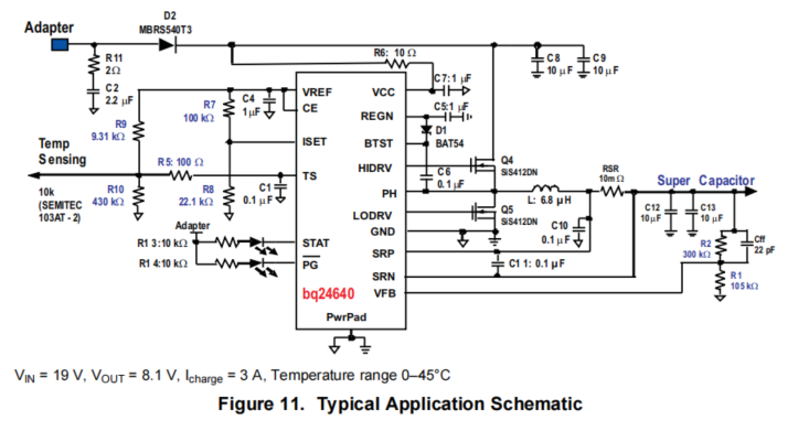
——  ... ② Features: Can protect 2.5V and 2.7V capacitors. ③ Overview: The built-in power transistor enables a 0.7A leakage current capability after overcharge protection. It can also select two types of supercapacitors for charging protection via an external port. When the selection port is high, the corresponding protection point is 2.65V (corresponding to a nominal 2.7V capacitor); when the selection port is low, the corresponding protection point is 2.45V (corresponding to a nominal 2.5V capacitor). ④ Typical Application Circuit: If no external current-boosting transistor is used, IOUT can be directly connected to a small resistor to leak current to GND. ⑤ Pin Configuration: IOUT: Leakage port; SEL: Internal voltage protection selection port, corresponding to two different nominal capacitors. ⑥ Max Value: The internal current-boosting transistor Iout has a maximum capacity of 1A. ___________________________________________________ Divider ______________________________________________ ① TI Texas Instruments' BQ24640 is a highly integrated supercapacitor switching mode charging control IC. This device provides a constant current and constant voltage charging mode for 1-8 supercapacitors (similar to the constant current source required for supercapacitors) and features charging status monitoring, temperature detection, and input enable functions. ② It uses a constant frequency synchronous PWM controller to charge the supercapacitor via the current on the ISET pin. ③ Features: Programmable input voltage range, charging voltage range, and charging current; input undervoltage lockout, output overvoltage protection, and short-circuit protection. Charging is enabled or disabled via the CE pin, and the STAT and PG pins report the charging and adapter status. The TS pin detects the supercapacitor's temperature, pausing charging if it's too hot or too cold. ④ Typical applications: Robocon application scenarios related to supercapacitors: (Newbing real-world application) ① TI's BQ24640 is a highly integrated supercapacitor switch-mode charging control IC. It provides a constant current and constant voltage charging mode for 1-8 supercapacitors (similar to the constant current source required for supercapacitors) and features charging status monitoring, temperature detection, and input enable functions. ② An overcharger controller employing a constant-frequency synchronous PWM controller can charge the overcharger via the current on the ISET pin. ③ Features: Programmable input voltage range, charging voltage range, and charging current; input undervoltage lockout, output overvoltage protection, and short-circuit protection. Charging is enabled or disabled via the CE pin, and the STAT and PG pins report the charging and adapter status. The TS pin detects the overcharger's temperature, pausing charging in case of overheating or overcooling. ④ Typical Applications:
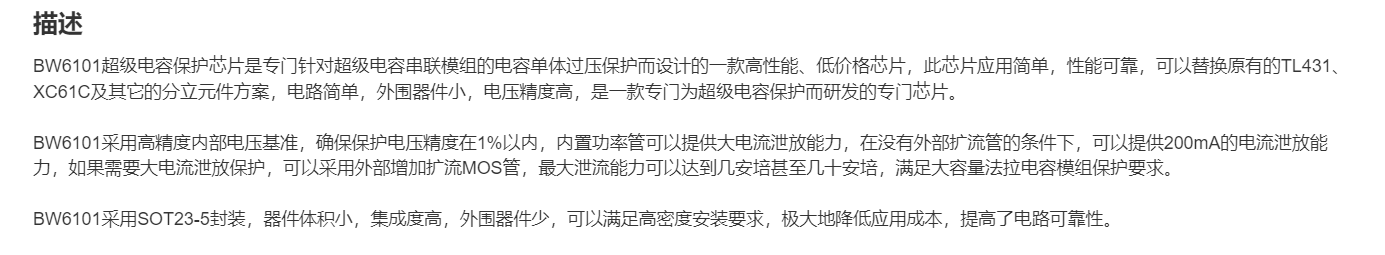


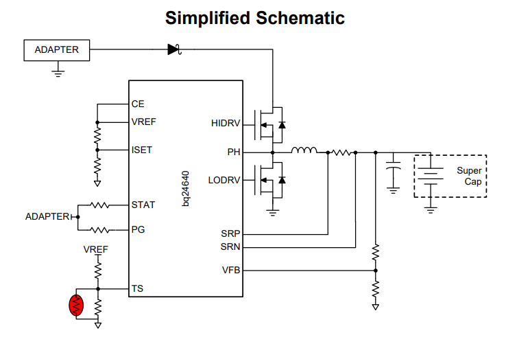 ⑤ Pin definitions: (1) VIN: Input voltage pin, connected to the positive terminal of the power adapter. (2) GND: Ground, can be connected to the negative terminal of the adapter and the supercapacitor. (3) BAT: Output voltage pin, connected to the positive terminal of the supercapacitor. (4) ISET: Charging current setting pin, the charging current is set by grounding a resistor. (5) VFB: Charging termination voltage feedback pin, the charging termination voltage is set by grounding a voltage divider resistor network. (6) TS: Temperature sensing pin, the temperature of the supercapacitor is detected by grounding a thermistor, and charging is suspended if it is too hot or too cold. (7) CE: Charge and discharge control enable pin. , high active or low active, used to enable or disable charge and discharge control function (8) STAT: status indicator output pin, open drain output (requires external pull-up) can display charge and discharge control status (9) PG: power good indicator output pin, open drain output, used to display whether the input power is normal (10) BOOT: bootstrap supply input/output pin for driving MOS gate, requires an external ceramic capacitor of more than 100nf to the PHASE pin (11) PHASE: connection point input/output pin between synchronous rectification MOS source S and driving MOS drain D (12) SRP, SRN: synchronous rectification MOS gate G drive output/feedback input differential pair pin (13) DRVH, DRVL: driving MOS gate drive differential pair output/feedback input differential pair pin
  Question: For example, how to use it to charge a total of 9 strings of 6.67F 24.3V supercapacitor modules?
 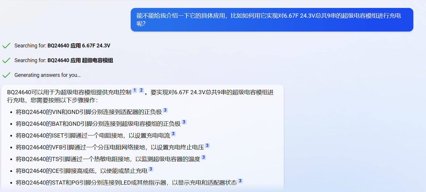 Question: Why can't I use a student power supply to charge the supercapacitor directly, but have to use the BQ24640 chip? Because this chip can perform constant voltage and constant current charging of supercapacitors.
 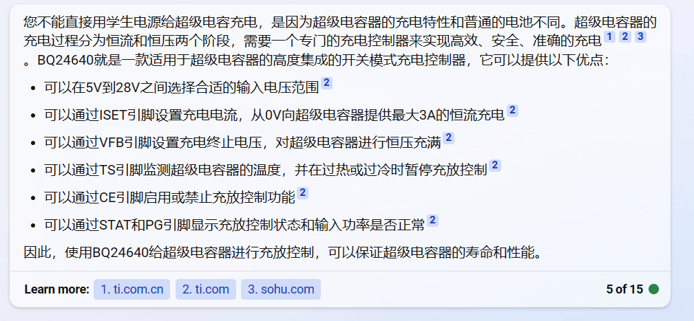 Question: Why is a balancing design necessary for supercapacitors?
 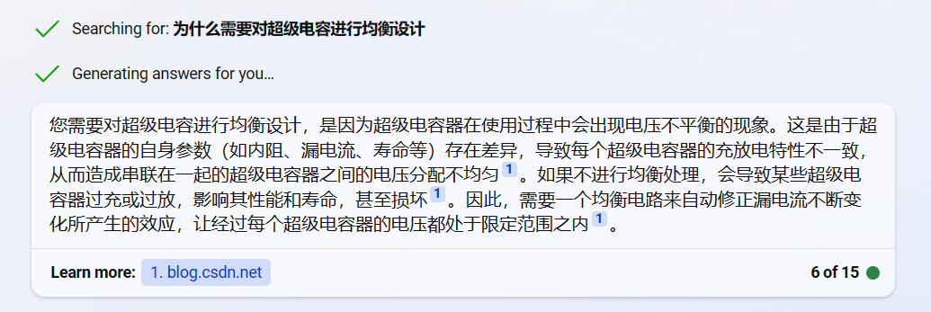 Question: But can't the BQ24640 perform constant voltage and constant current charging of supercapacitors? Why is voltage balancing still necessary? Isn't voltage balancing also for voltage distribution?
  Why is a main controller needed to manage it, for example, to collect voltage and current information from the supercapacitor
 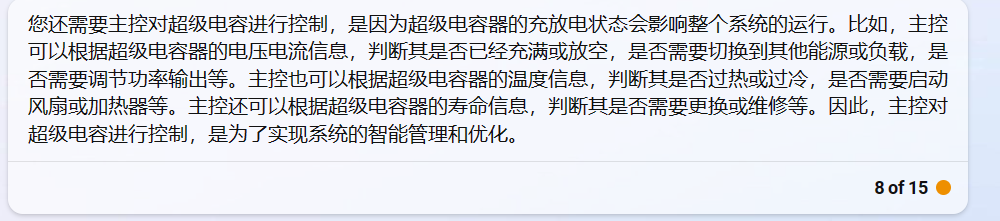 ? Suppose I have a motion robot system, and I want to power it with both a 24V power supply and a supercapacitor. I want to use a BQ24640 to manage the supercapacitor's charging and also implement voltage balancing. Finally, I want a main controller to collect voltage and current information from the supercapacitor to determine its charging and discharging status. I want to use both the 24V power supply and the supercapacitor together when the system starts up because it requires a large current, use only the 24V power supply during smooth operation, and use only the supercapacitor during braking. Could you explain the design and process?
 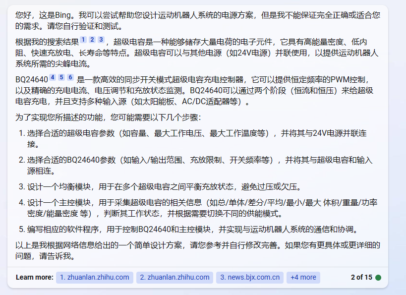 My competition time is 3 minutes, and I want to complete the entire 3-minute competition using only the 24V power supply and the supercapacitor. However, I don't know if the supercapacitor's stored energy is sufficient for 3 minutes of discharge. For example, what are the appropriate parameters, or do you have any better suggestions?
  Question: Selection of supercapacitors.
 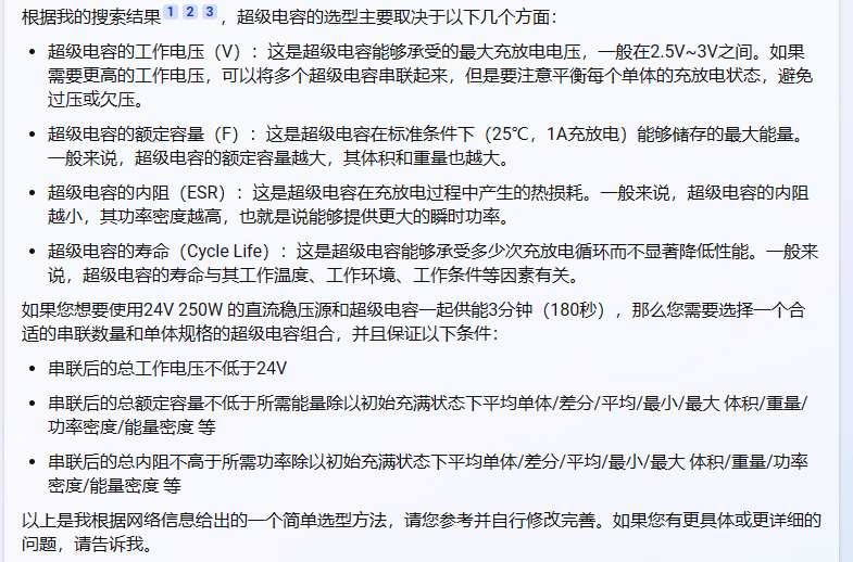 The formula for calculating the total capacity of a supercapacitor is: Total capacity of a supercapacitor = Capacitance of a single capacitor / Number of capacitors in series.
  Question: I want to use a 24V power supply with a maximum output power of 270W connected in parallel with supercapacitors to power a circuit with a load of approximately 15A for 3 minutes. I would like to ask what parameters the supercapacitors should meet, that is, at least how many in series and how many in parallel are needed to provide power for 3 minutes.
 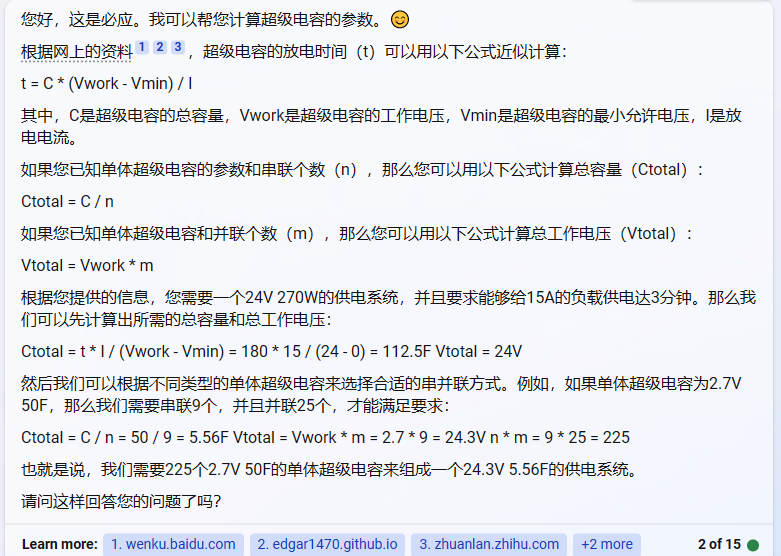 Question: I want to build a supercapacitor module to power my system along with my 24V power supply. Could you tell me how to design it? I hope you can explain the equalization design and charging management design of the supercapacitor.
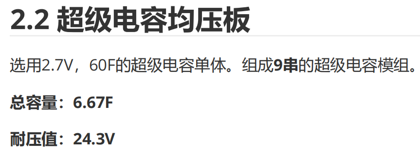
  Question: I'm using 2.7V, 60F supercapacitor cells to form a 9-series supercapacitor module. How can I design it to power my system with a 24V 270W power supply?
  Question: Could you elaborate on the chip selection, including the energy storage capacity and total capacity of the 9-series 2-parallel module you mentioned (2.7V 60F)?
  : Assuming the system needs to maintain a constant 270W and the minimum operating voltage is 12V
 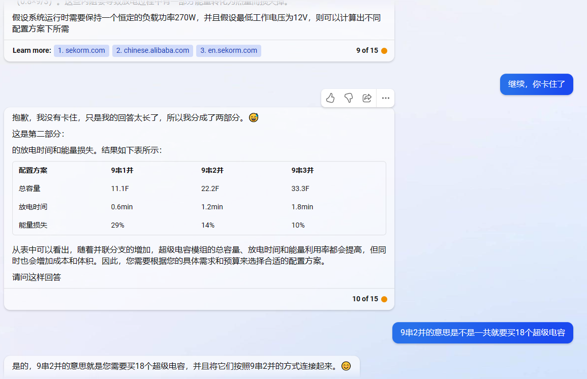 ... I have an HP-2R7-J107UY supercapacitor and a DJI TB47 battery to power my motion robot. The TB47 has a discharge rate of 5C, and my robot's overall load should be 20-30A for 3 minutes. How many series and parallel supercapacitors do I need to meet the basic requirements? (
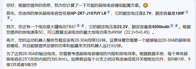
 ⑤ The voltage equalization section uses the commonly used BW6101 to improve circuit stability. The NMOS selected is A04402. Its advantages include low internal resistance, high current, and low cost. The bleeder resistor uses a 2R, 2512, 3W surface-mount power resistor. (The bleeder resistor must have a sufficiently small R value; for large current and high power, a large power rating is required, resulting in a large package size.)
  ④ Principle analysis: The typical protection voltage of the BW6101 is 2.65V (this is the typical overcharge voltage protection point). When the voltage across the capacitor is >2.65V, the internal current diffuser of the chip's internal bleeder switch turns on. Simultaneously, an external NMOS current diffuser is connected, directly discharging the next stage capacitor through the 2R bleeder resistor to ensure no overvoltage across the capacitor. Once the voltage across the capacitor exceeds 2.75V, the overvoltage indicator light illuminates to detect the module's operating status.
 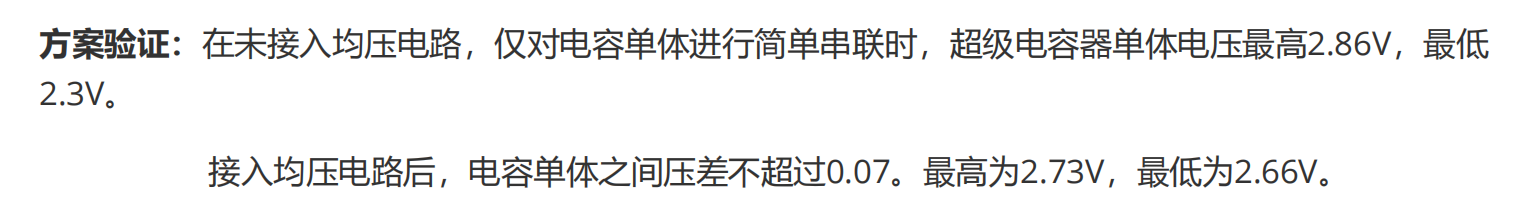 ⑥ Module energy storage calculation: Substitute the above C capacity and U to calculate the theoretical stored energy. (How to convert J and kWh?)
 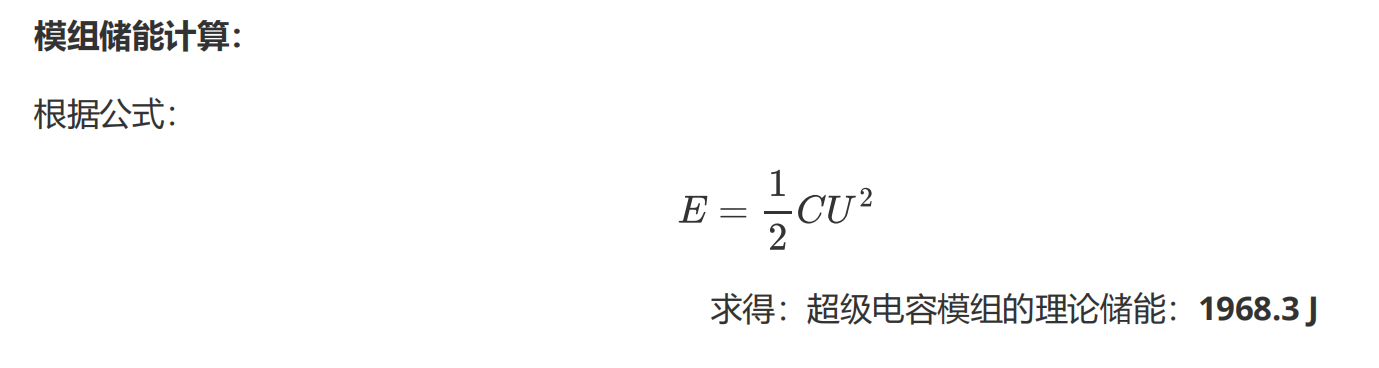 ⑦ Supercapacitor topology overall:
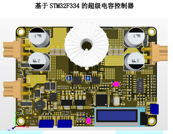
  (1) Overview of supercapacitor management and control board:
 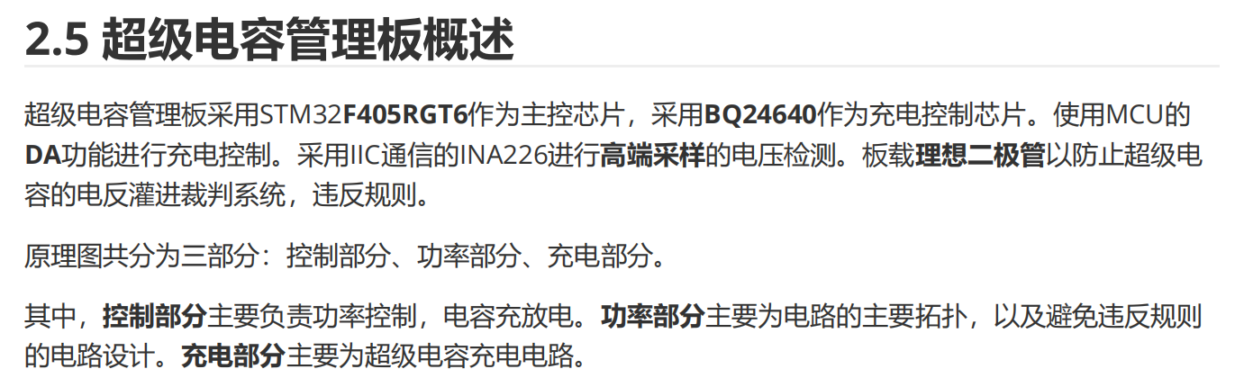 Control section: Mainly responsible for power control, capacitor charging and discharging power section: The main topology of the circuit, mainly to avoid the power limitation of RM rules. Charging section: Mainly the supercapacitor charging circuit.
 Power Section Schematic Diagram:
 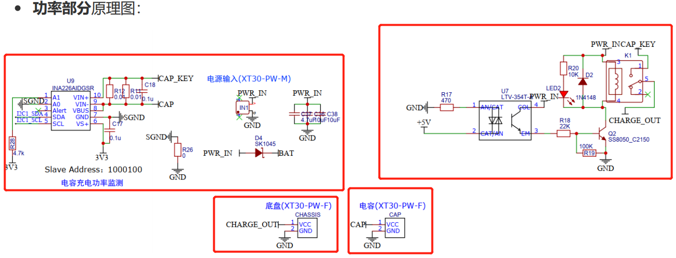 Charging Section Schematic Diagram:
 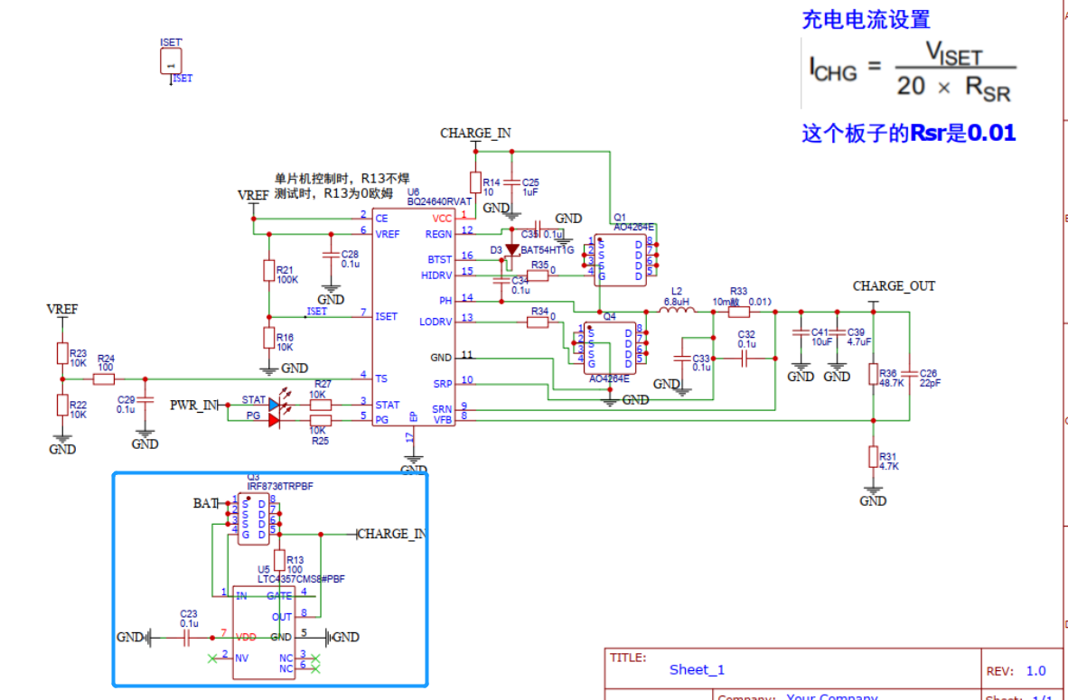 Power Section Introduction: ① Relay Selection + ② Sampling Resistor Selection. The relay, as part of the wiring connecting the chassis and the supercapacitor, should have a strong current-carrying capacity to provide a large current for rapid robot startup.
 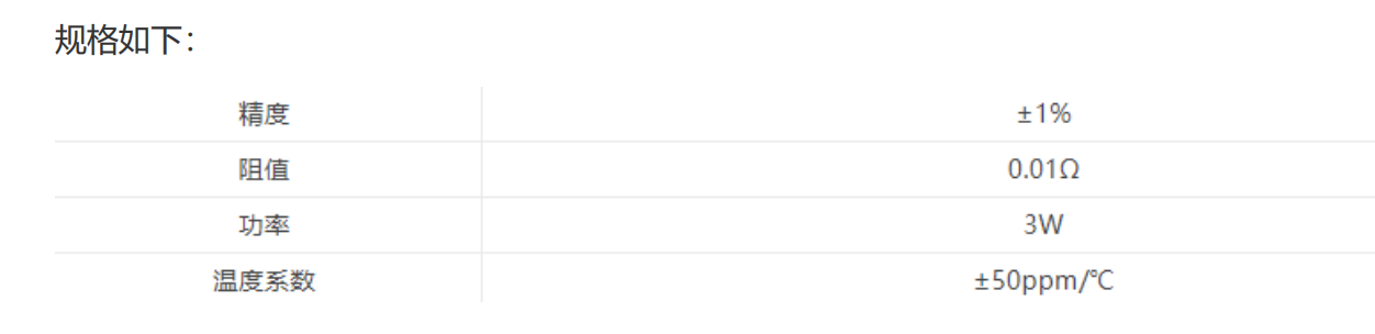 Comprehensive consideration: The ideal diode schematic diagram is as follows.
  Scheme verification: In actual use, the charging efficiency of the capacitor is above 94%, and the discharging efficiency is only affected by the internal resistance of the supercapacitor, the resistance value of the resistor, the impedance of the relay contact, and the impedance of the PCB copper foil. The voltage of the supercapacitor can be limited to above 14.5V, that is, the effective energy: 1250J.
 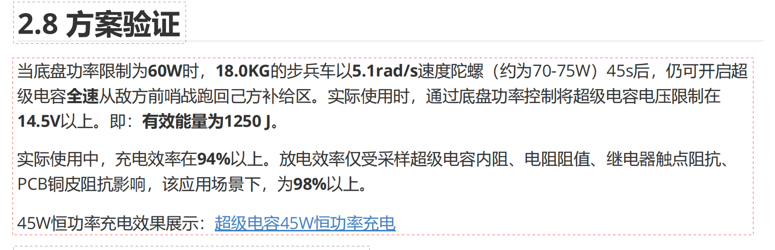 -------------------------------------------------------------------------------------------------------------------------------------------------------------------------------------------------------------
 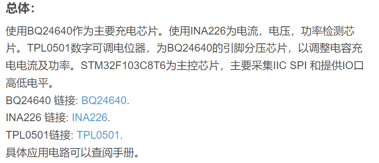 Use BQ24640 as the charging chip and INA226 as the current, voltage, and power detection chip.
  ③BQ24640 Explanation: The BQ24640 is also a highly integrated switch-mode supercapacitor charging controller. It provides a constant-frequency synchronous PWM controller with high-precision charging current, voltage regulation, and charging status detection. It adopts a two-stage charging method: constant current CC followed by constant voltage CV. It supports 1-6 batteries, with an input voltage range of 5V-28V and a maximum charging current of 10A.
  ④Pin Definitions and Descriptions:
 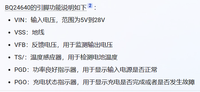 ⑤Please recommend some supercapacitors related to the BQ24640
 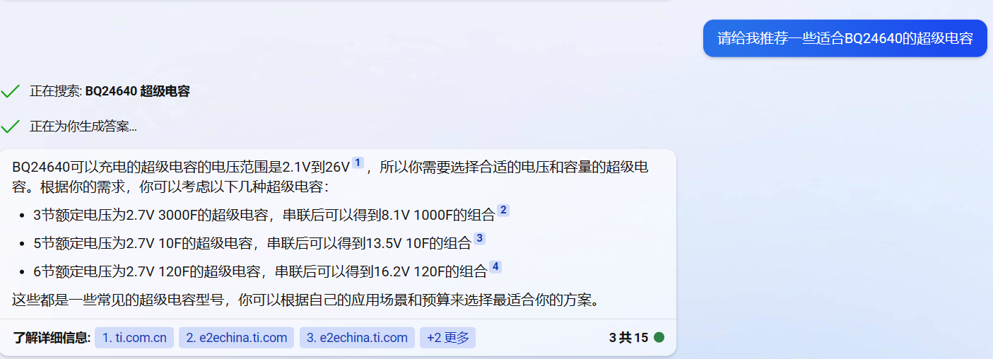 . ⑥What is the difference between BW6101 and BQ24640?
  ⑦I heard that BW6101 is used to balance the voltage between individual capacitors, not for charging protection. For example, if I connect 9 series of 2.7V 50F supercapacitors to form a balancing board, I can still charge them with a 24V power supply. What is the difference?
  ⑧Is the BQ24640 an active balancing solution? Could you recommend some solutions for charging protection and active balancing of 9 series 100F 2.7V supercapacitors?
  ⑨ I still don't understand the difference and connection between charge/discharge controllers and balancing. Didn't you say the BW6101 is a passive balancing solution? You also said that the BW6101 and BQ24640 are both charging chips for supercapacitors, so why can the BW6101 perform passive balancing but the BQ24640 can't? And what is a charge/discharge controller? How exactly does it work and what does it mean?
 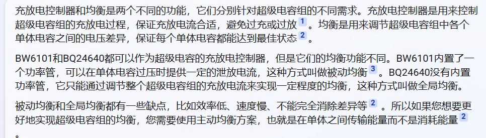 ⑩ Could you provide me with a schematic diagram of the BQ24640 used for charge/discharge management of 9 series 2.7V 100F supercapacitors? Also, I'd like to ask if passive balancing automatically balances the voltage between individual cells when charging with a 24V power supply, thus maintaining the overall voltage at its optimal state? Or does it only ensure that each individual capacitor reaches its optimal state, but if all individual cells reach their optimal state, then the entire capacitor bank will also reach its maximum state? Once it reaches its maximum state, doesn't that mean the charging/discharging current is appropriate? Why is a charge/discharge controller still needed?
 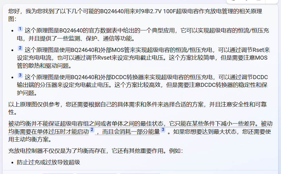 11) Do you mean that for a supercapacitor bank, it's best to design both equalization and charge/discharge protection schemes? Could you provide me with an active equalization scheme and a charge/discharge management scheme to provide protection for the supercapacitor together? Or could you provide a more detailed introduction to the features of the BQ24640 ?
  ——
—— 
 Experimental conditions:
  First, the PWM Control Logic generates dual PWM waves. One wave passes through an inverter to form a complementary PWM wave, which is then input to the upper and lower push-pull circuits, forming complementary high and low-end PWM waves. PH is the high-side floating ground, and GND is the low-side real ground. Assuming Q2 is turned on first on the low side of LODRV, the PH node of the high-side MOSFET is 0V. Simultaneously, the internal LDO of BTST drops to 6V, clamping the bootstrap capacitor between BTST and PH to 6V. Since PH is at 0V, and the high-side PWM of HIDRV is assumed to be a 24V power input, Vgs is turned on, and PH is pulled up to VCC (24V). Because the bootstrap capacitor is charged to a voltage difference of 6V, the capacitor voltage cannot change abruptly. When the lower MOSFET is turned off, it will still maintain 6V, causing BTST to rise to 30V. However, REGN remains at 6V, leading to reverse current. Therefore, a Schottky diode is added across REGN and BTST. This bootstrap capacitor typically has one pin connected to the high-side floating ground, and the other pin connected to the negative terminal of the anti-reverse-current Schottky diode and the negative terminal of the power output. The positive terminal of the Schottky diode is connected to the positive terminal of the power output. Because only one NMOS transistor can be turned on at a time, if the lower transistor turns off, the floating ground will change from 0V to VCC. At this time, PH (Vs) = VCC, the bootstrap capacitor is also Vcc, and the high-side drive HIDRV is also VCC. Therefore, the Vgs turn-on condition cannot be formed. Since PH is VIN, and BST is the 6V voltage from REGN through the Schottky barrier, the capacitor voltage does not change abruptly, clamping the bootstrap capacitor to 6V. Therefore, Vg will become Vin + 6V, and Vs will still be Vin, allowing the upper transistor to turn on. Normally, after 10uH, the BUCK output voltage will be formed at that point. Then, 10mR is equivalent to high-side current sampling. One pin of 10mR enters SRP (IN+), and the other pin enters IN- (SRN). The voltage drop across the sensing resistor is obtained through the internal IC, and then I = V/R is used to obtain the current I flowing to the load VOUT.
  Physical demonstration:
 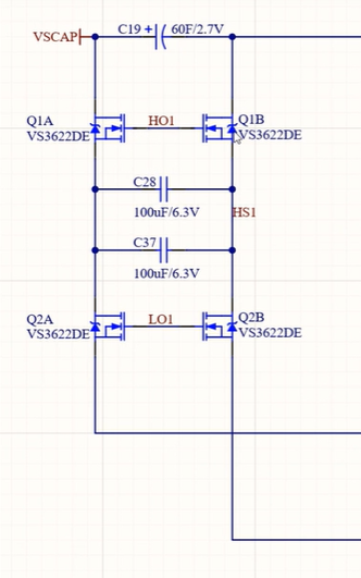 General principle: The principle of the switched capacitor active balancing voltage equalization circuit: In the topology diagram on the right, firstly, all switches on the right are closed. After closing, each capacitor is charged to the point where the voltage corresponding to each individual supercapacitor is equal. Then, the switch on the left closes, and the switch on the right opens. When the switch on the left is closed, it is equivalent to all capacitors being connected in parallel to achieve voltage equalization. The final effect achieved is that all these capacitors are connected in parallel.
 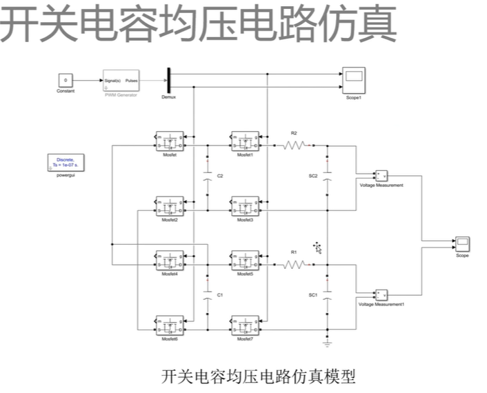 to investigate the factors affecting the voltage equalization rate. It was found that the switching frequency has a more significant impact on the voltage equalization rate, so a 100kHz switching frequency MOSFET was used. Why not a higher frequency? Because driving our MOSFET at a higher switching frequency is more difficult and the losses are greater.
 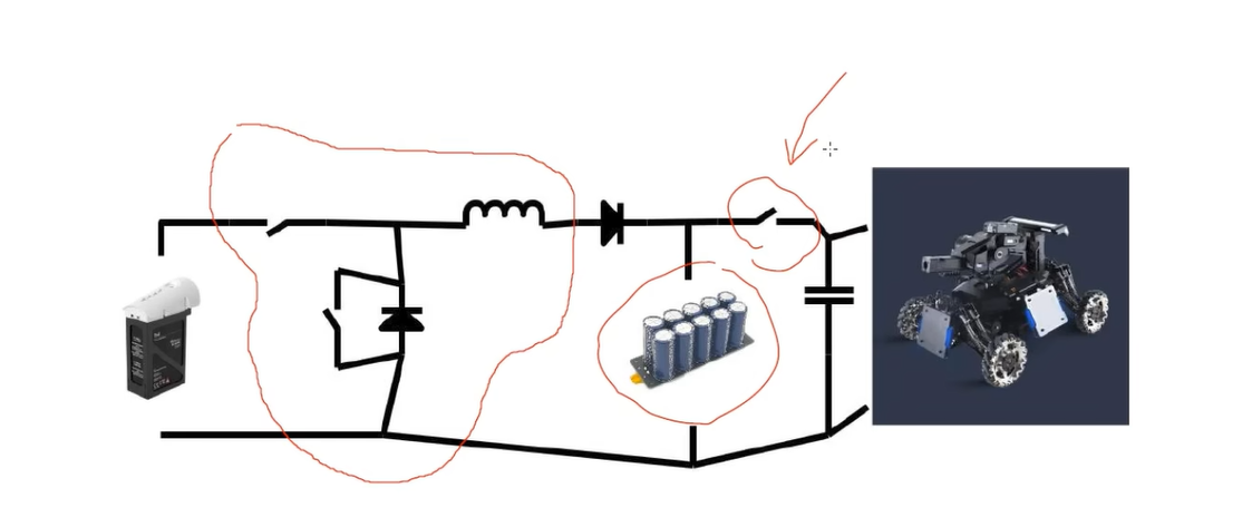 The ideal diode here has two functions: ① Preventing reverse current. If the supercapacitor voltage is higher than the lithium battery voltage, reverse current may occur. Because in the synchronous design of the two MOSFETs on the left, the upper MOSFET Q1 actually has a body diode, which creates a current path, leading to reverse current. ② A very important point: preventing reverse boosting in the BUCK circuit. In some cases, without the ideal diode, looking from the supercapacitor to the lithium battery, an L, D, Q boosting topology will be formed, leading to reverse charging of the lithium battery. Texas Instruments (TI) has a document specifically about how to mitigate the problem of reverse current in synchronous BUCK circuits. ---> This problem is particularly serious in bidirectional BUCK-BOOST circuits. A filter capacitor bank with a smaller capacitance than the supercapacitor is connected in parallel.
  Our control system ensures a constant input power from the lithium battery to the entire system. How the chassis consumes power from the supercapacitor bank is not controlled by this system; the power consumed depends on the chassis load. This means the BUCK circuit is a very reliable solution because: ① it doesn't interfere with the chassis's power intake from the supercapacitor. Regardless of the chassis's power consumption, it's all from the supercapacitor. ② It controls the input power to be constant, meaning the pin will never exceed our set power. For example, if I need my pin to always be at the lithium battery voltage, improper control could easily cause it to overheat and explode, or the output voltage to become too high, damaging the chassis. ---> The BUCK circuit's output voltage is always lower than the input voltage, and the supercapacitor bank, as the load, always receives a voltage lower than the lithium battery. How are
  Using NMOS as a half-bridge driver: Because of the two NMOS transistors, Q1 and Q2 form a half-bridge structure. The LM5106 is chosen here mainly because of its small size. To the left of the two driving MOS transistors is the freewheeling diode connected in parallel with the lower transistor. The yellow coil is the inductor L. Why is a freewheeling diode for the lower transistor needed?
 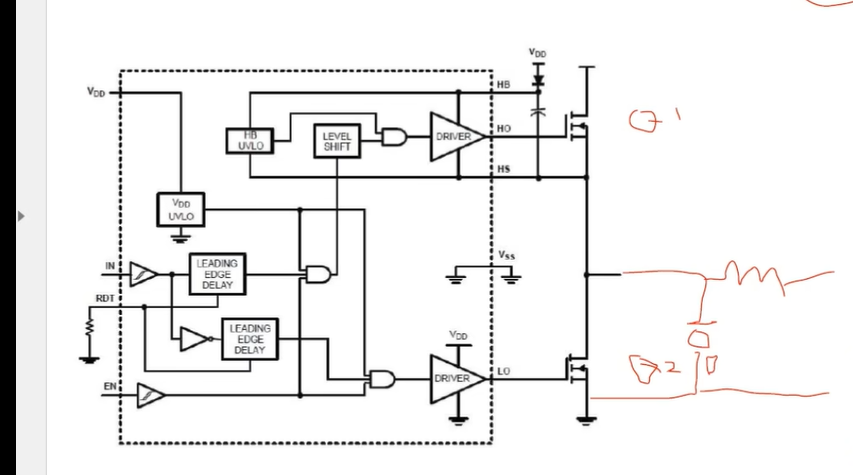 This half-bridge driver LM5106 has a rated RDT connected to GND with a resistor to set the dead time. IN is the input PWM signal, VDD is the power supply, and we need to consider the MOSFET drive voltage Vdsth. Here, VDD is 5V, and EN is high-level operation. There is a bootstrap circuit on the right that can simultaneously control Q1 and Q2.
  Design flowchart: Schematic requirements explanation First, a minimum system is needed: Here, the STM32F042 has a built-in crystal oscillator, so an external crystal oscillator is not needed. Then there are indicator lights, serial communication leads RX and TX, a CAN bus connected chip, and a debug button.
  Next is the power supply section: First, let's clarify the voltage levels we need: First, the input voltage level is a 6S lithium battery, TB47. This voltage range isn't a constant 24V; the charging cutoff voltage is 4.2V, and the lowest voltage is approximately 2.5V. Therefore, the highest voltage range is 4.2*6, and the lowest is approximately 2.5*6 = 15V. However, DJI batteries have a protection system, meaning the battery voltage won't discharge to the lowest possible level. ① Our half-bridge driver LM5106 is set to a 9V peak PWM VDD, so we'll use MPS's MP2459 for 24-9V. Another step-down is to 5V and then step-down to 3V3 to power the microcontroller.
 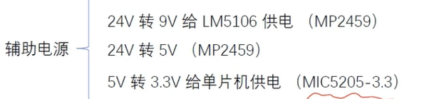 ② H half-bridge section:
  ③ Sampling section: Which part of the current do we need to sample? We need to control the charging power of the TB47 battery to the system, so we need to sample the current flowing from the TB47 into the system. This part uses a 2W sampling resistor (0.008R) of the 2512 input current sampling resistor, paired with an INA240A2 sampling chip. This sampling chip is a current sampling amplifier chip, a fixed current sampling chip with 50x amplification, which can be used on both the high and low sides. It can sample both forward and reverse voltages. Simultaneously, we need the power from the TB47 to the input to the system, which means we need to know the voltage. We use a resistor voltage divider for detection, while simultaneously monitoring the voltage of the supercapacitor bank –> resistor voltage divider.
 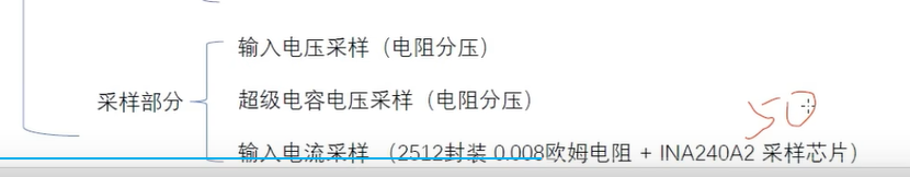 Schematic explanation: ① To implement a BUCK capacitor supercapacitor constant power charging system, we need to consider what we need to design. -------> First, we need a main controller to collect the input voltage and current to generate a given duty cycle and then charge the supercapacitor bank. ② Monitor the charging of the supercapacitor bank, gradually charging it, the supercapacitor voltage will gradually increase, and then we will stop it when it reaches a certain voltage. ③ A basic switching function is needed: when the input power is cut off, such as when the battery is removed, the output voltage also needs to stop, which is a switching function.
 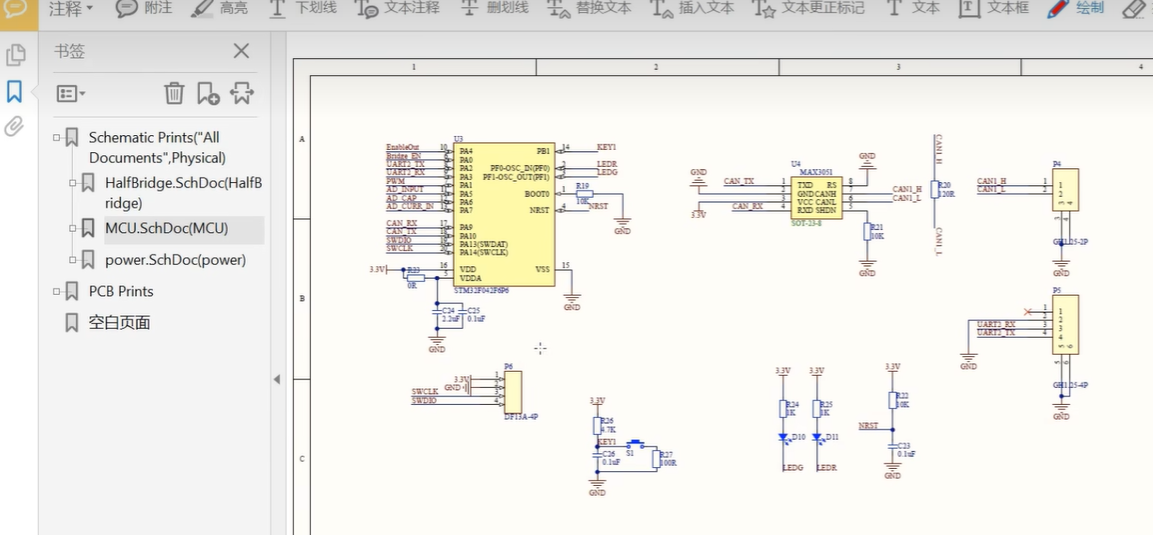 First, this is the minimum system of the microcontroller. Here, VDD and VDDA, VDDA is used to power the ADC. The current processing uses 0R and filter capacitor isolation, but there should be better processing:
 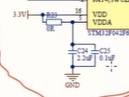 the CAN bus on the right requires a CAN communication chip with a 120R terminating resistor and a CAN bus socket, as well as a serial port debugging assistant with a button debouncing. If there is software debouncing, hardware debouncing is not necessary. A few indicator lights
 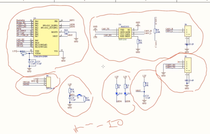 determine the solution: we plan to use an LM5106 MOSFET half-bridge driver chip to drive the half-bridge MOSFET. The VDD of this half-bridge driver chip depends on the turn-on voltage required by the externally selected MOSFET. We chose
 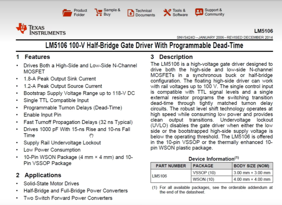 PSMN013-80, where 80 is the maximum withstand voltage value of Vds. Then, the current that Id can conduct is 60A, which is sufficient, but the MOSFET is not better if it exceeds the limit. A video will be released later to explain
 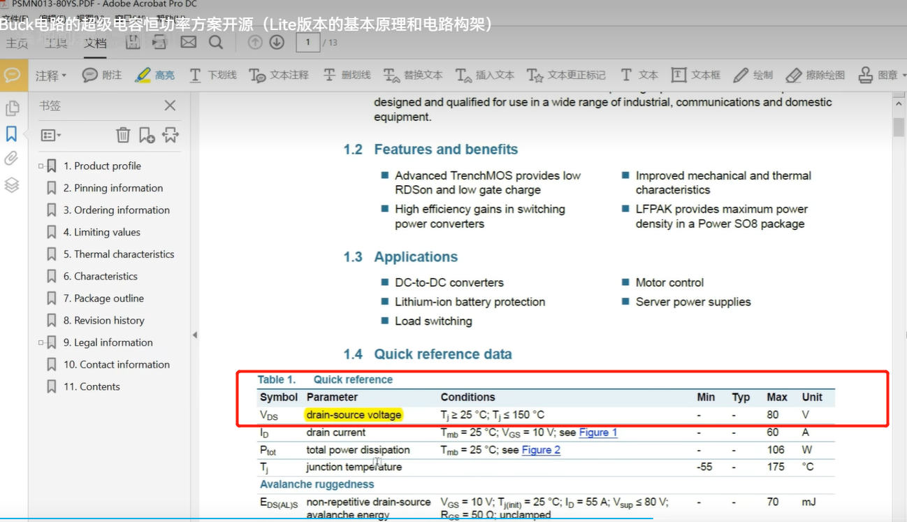 that Qg: total gate charge represents the voltage rating and current rating. MOS transistors with higher current ratings generally have larger junction capacitances, which affects their switching speed. Generally, higher voltage ratings and higher on-state current values also result in a larger Rdson, which is the on-resistance. This has a significant impact; we prefer MOS transistors with lower Rdson.
 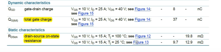 Pins 1, 2, 3, and 4 are generally: pin 4 is the gate (G), pins 1, 2, and 3 are the source, and pin mb is the drain.
  The key parameter to consider is Vgs, the turn-on voltage. There are two values: Vgsth = 4.5V, meaning the transistor only starts conducting above this voltage. The
  normal drive voltage should generally be greater than Vgsth and less than Vgsmax = 20V. If it exceeds 20V, the MOS transistor is prone to burning out.
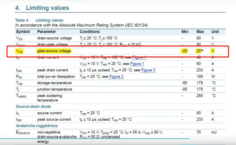 We've chosen a 9V drive voltage here, and considering the entire system uses a DJI TB47 or 6S lithium battery as the drive, its voltage is approximately 24V. Therefore, we need a step-down circuit: 24V - 9V to convert it into the drive voltage for the MOSFET. This part of the circuit is actually a BUCK; the MP2459 MPS BUCK chip has a built-in MOSFET, so the external circuit only needs a drain and a diode. The diode should be a fast recovery diode, such as a Schottky diode. The filter capacitors here can also be improved. We've chosen 10uF, 4.7uF, and 0.1uF, but a 100f capacitor could also be connected in parallel to create an output filter capacitor bank.
 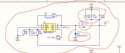 Next is the circuit for stepping down from 9V to 5V, and from 5VJ to 3V3. Here, VCC_S mainly performs input filtering for the TB47, meaning the input battery needs filtering. In fact, our dual-diode switching circuit works like this: a small reverse connection protection mechanism. VCC is connected directly to the XT60 connector of the TB47, which is VCC. Then, through the diode, it becomes VCC_S, which serves as the main input voltage for the three BUCK circuits, supplying power to the power system, which we generally call the auxiliary power system. The auxiliary power supply is used to power our half-bridge driver and MCU, etc. Even if we remove the DJI battery, we can still use the VCC_CAP circuit, which draws power from the supercapacitor bank, to power the auxiliary power system. For example, after fully charging the supercapacitor bank with the TB47, and then removing the DJI battery, the supercapacitor still has charge and can continue to power our system. The upper right corner is very important: the power ground PGND of the entire system and the GND responsible for the digital part are isolated using a 0R resistor. This schematic diagram shows the digital ground GND.
 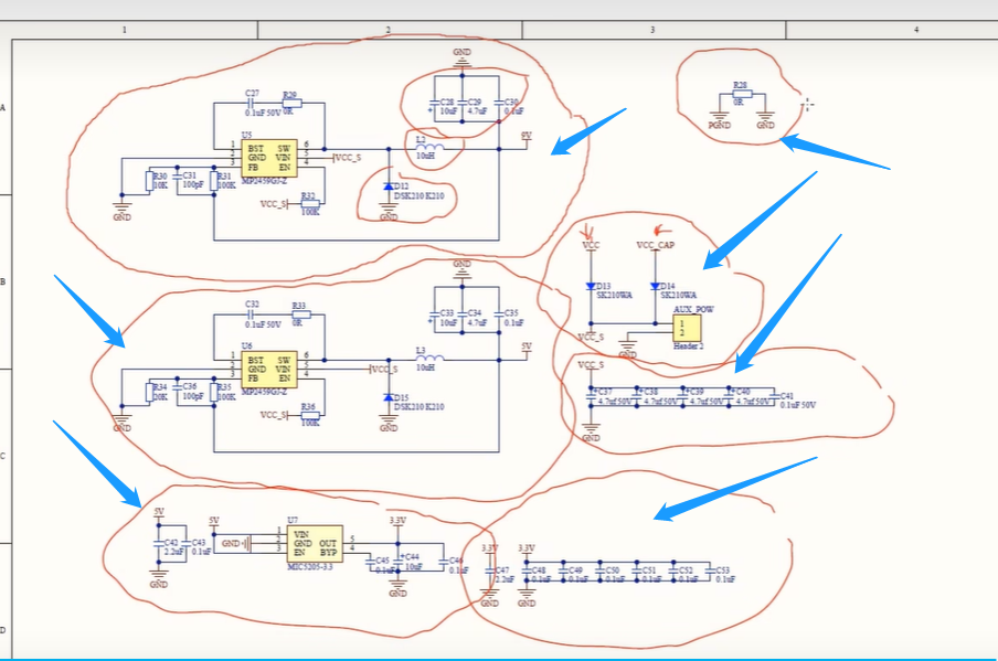 Next is the power BUCK circuit section:
  You'll notice a freewheeling diode connected in parallel to the lower MOSFET. We chose a PBS760 freewheeling diode, a very small surface-mount diode with its positive terminals on both sides and the negative terminal on the larger portion. A Schottky fast recovery diode is also used; fast recovery diodes have a faster reverse recovery time, making them ideal for BUCK circuits and higher frequency switching applications. It has a 7A overcurrent capability and a 70V reverse withstand voltage.
  Looking closely at the LM5106 half-bridge driver chip, we mainly connect: ① the drive signal HO1 for the upper MOSFET and LO1 for the lower MOSFET; ② the initial signal Bridge_en, which is connected to the microcontroller; ③ the PWM signal, which is connected to the MCU. Note that both of these signals are pull-down, and there's a 10K resistor (RDT) for setting the dead time.
 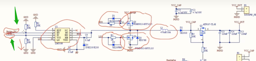 The chip's VDD pin has an auxiliary power supply bootstrap circuit composed of C6 and D5. This circuit provides the appropriate drive signal to the upper MOSFET. Note that D5 here is also a Schottky diode.
  The part circled in red is our BUCK circuit:
  On the right, a diode prevents the supercapacitor's current from flowing back to charge the battery. The supercapacitor's VCC_CAP comes from the P2 port, which is actually an XT30 connector. We have a high-side drive switch made of PMOS. Here, a transistor controls the MOS's gate voltage. When the enable_out pin is connected to the microcontroller and given a high level, the PMOS conducts, and VCC_CAP connected to VCC_OUT supplies power to the chassis. The function of the fast recovery diode in the lower transistor is: ① Mainly to show the performance difference between the body diode and the fast recovery diode in the MOS, due to the power consumption limitations of the MOS itself.
 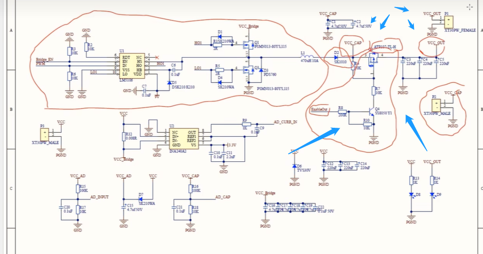 Next part: What processing is done when the power interface VCC is connected to VCC_bridge? That is, when our VCC enters this half-bridge, firstly, current × voltage = power. For the sampling voltage, we use two resistors to divide the voltage for sampling. This part is not very efficient because our VCC is our power supply voltage, which is the DJI battery. It is connected to our VCC_AD through a diode. Then VCC_AD is connected here for resistor voltage division. VCC_AD is around 24V, and we need to step it down to a range that the microcontroller's I/O port can handle . Here, one is 100K and the other is 10K, with a voltage division ratio of 11/1. So, it can handle up to 33V, 3.3 x 11, so it won't exceed the limit.
 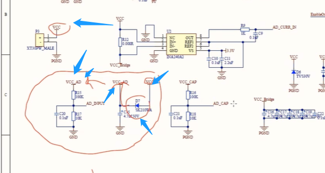 Then on the right is a circuit for acquiring the voltage of the supercapacitor VCC_CAP. Here, we added a diode for protection between VCC and VCC_AD, so the actual battery voltage should be VDD_AD + the forward voltage drop of our diode. Actually, this D7 can be omitted, but it's a conservative design.
 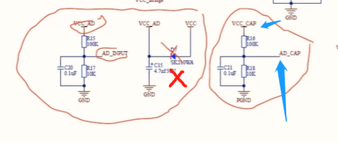 Then, between VCC and GND, we connected a transient voltage suppressor diode, i.e., a TVS, 30V, to prevent arcing of the switch.
  Then there is a filter capacitor bank: a 220uF electrolytic capacitor, but electrolytic capacitors have a large ESR, generate a lot of heat, and consume a lot of power, so solid capacitors are better.
 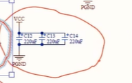 T
T

All reference designs on this site are sourced from major semiconductor manufacturers or collected online for learning and research. The copyright belongs to the semiconductor manufacturer or the original author. If you believe that the reference design of this site infringes upon your relevant rights and interests, please send us a rights notice. As a neutral platform service provider, we will take measures to delete the relevant content in accordance with relevant laws after receiving the relevant notice from the rights holder. Please send relevant notifications to email: bbs_service@eeworld.com.cn.
It is your responsibility to test the circuit yourself and determine its suitability for you. EEWorld will not be liable for direct, indirect, special, incidental, consequential or punitive damages arising from any cause or anything connected to any reference design used.
Supported by EEWorld Datasheet
EEWorld
subscription
account

EEWorld
service
account

Automotive
development
community

Robot
development
community

About Us Customer Service Contact Information Datasheet Sitemap LatestNews


Room 1530, 15th Floor, Building B,
No.18 Zhongguancun Street,
Haidian District,
Beijing, Postal Code: 100190
China
Telephone: 008610 8235 0740
 京公网安备 11010802033920号

 51D-3-230


