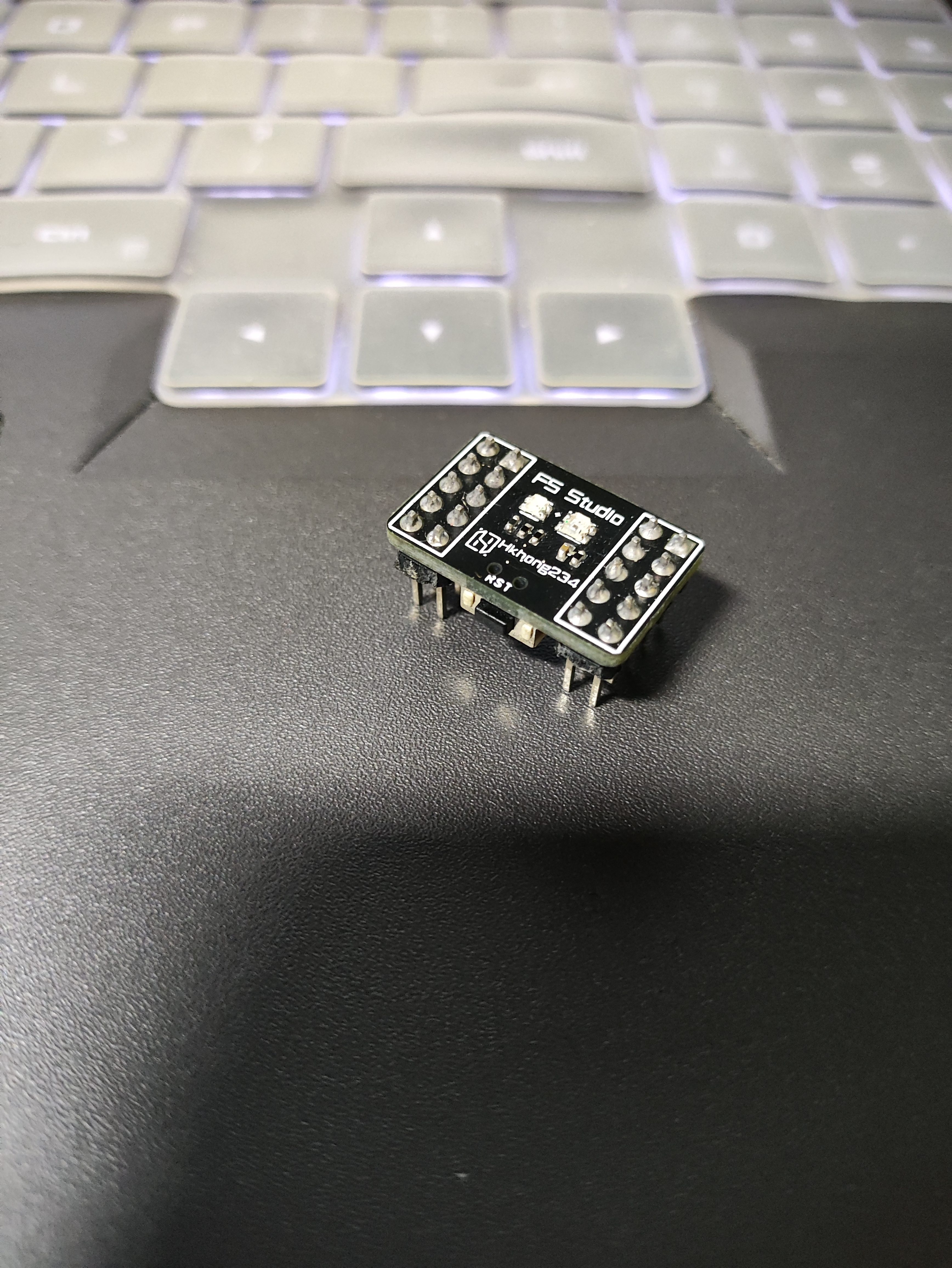
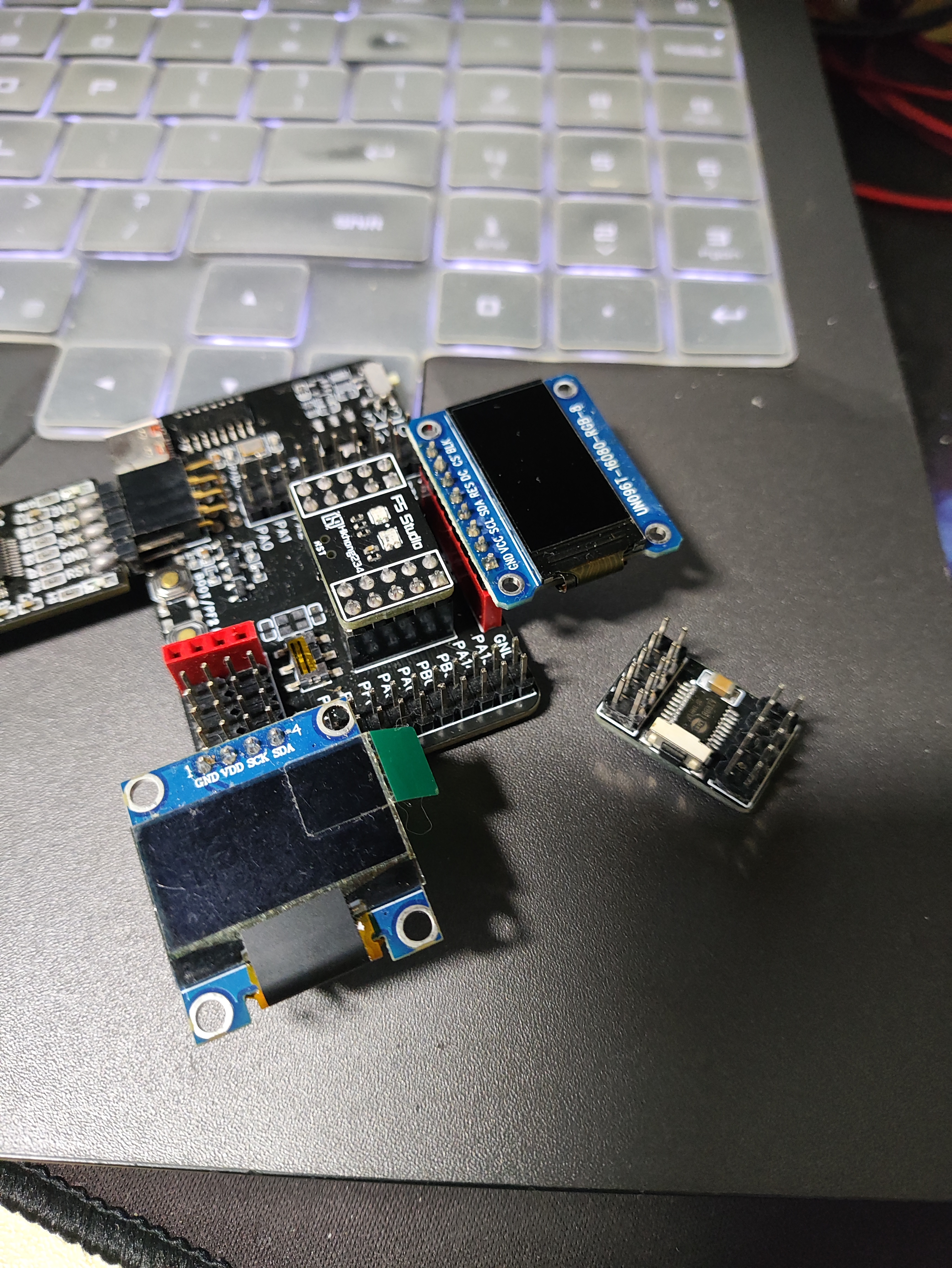
To facilitate my own development of the Air001, I designed this development board. The small board has one onboard RGB LED, one WS2812 LED, and one reset button. The baseboard has onboard reset and boot buttons, and exposes all I/O pins, including a row of I2C ports, one OLED interface, and one TFT direct-plug interface (all tested and working correctly).
The switch can toggle between 3.3V and 5V (Note: the 3V and 5V direction indicators in the picture are reversed; this has been corrected in the schematic).
Important notes:
Solder the LDO and DC-DC according to your preference.
The reset button on my current small board is a bit high; soldering the pin header board to the board will cause it to hit the button. You can replace it with a lower button.
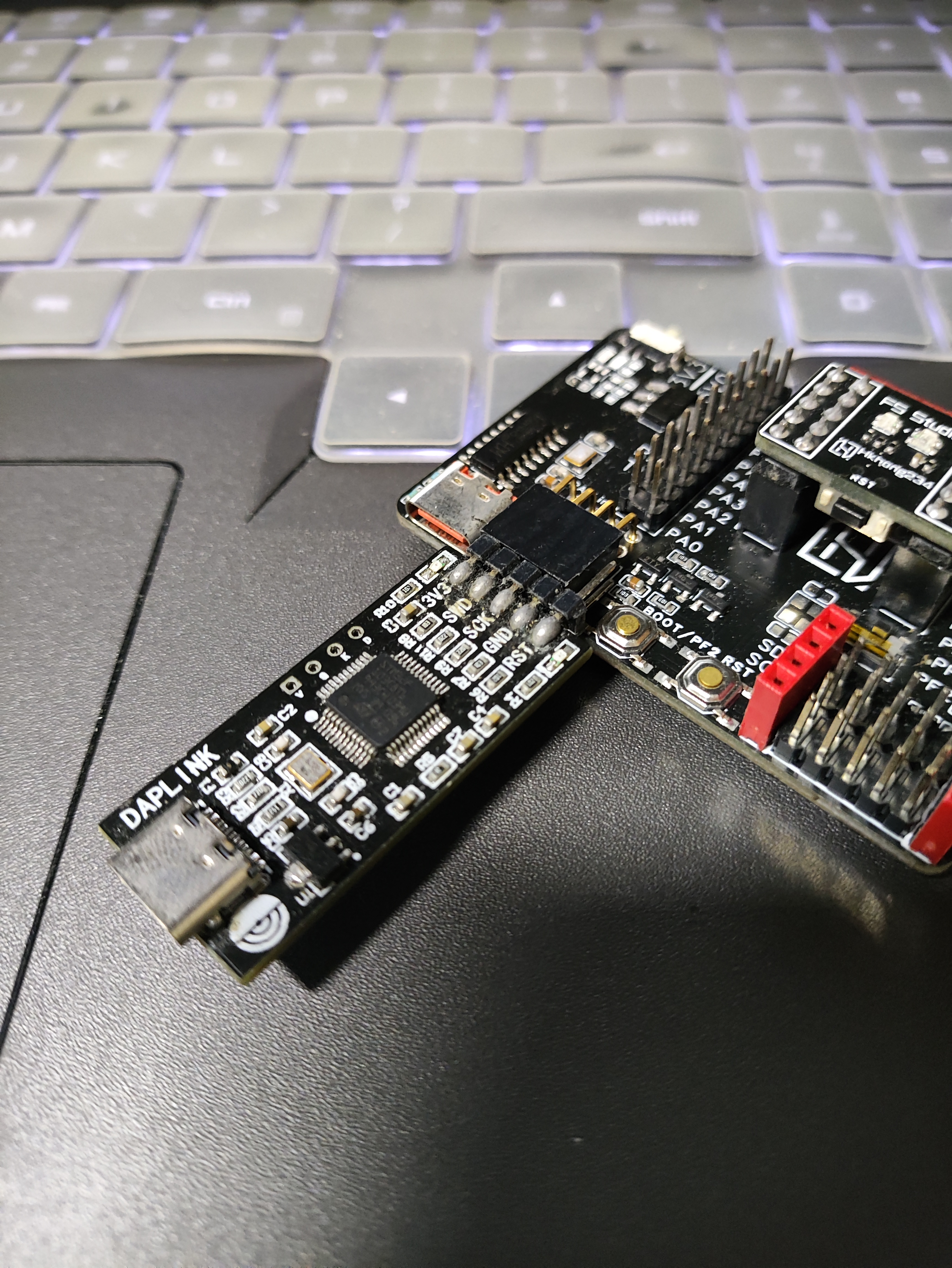
This project's baseboard is compatible with a DapLink LED purchased from Taobao; it cannot use a Heze DapLink LED.
PDF_air001 Minimal Core Development Board & Multifunctional Baseboard.zip
Altium_air001 Minimal Core Development Board & Multi-functional Baseboard.zip
PADS_air001 Minimal Core Development Board & Multifunctional Baseboard.zip
BOM_air001 Minimum Core Development Board & Multifunctional Baseboard.xlsx
97484
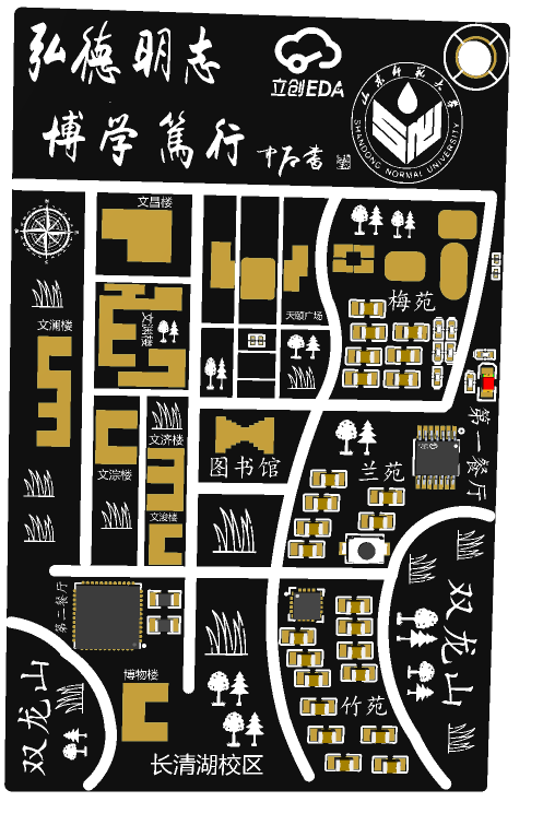
SDNU Campus PCB
Shandong Normal University Campus Map PCB
The front features the college logo, a floor plan of the school, and the school motto.
PDF_SDNU Campus PCB.zip
Altium_SDNU Campus PCB.zip
PADS_SDNU Campus PCB.zip
BOM_SDNU Campus PCB.xlsx
97486
#8th LCSC Electronics Design Contest# STM32-based Wireless Remote Control Dual-Vehicle Cooperative Control System
STM32-based wireless remote control dual-vehicle cooperative control system
Note: * Required fields,
please fill them in during the registration phase ↓
* 1. Project Function Introduction
This project is a wireless remote control dual-vehicle cooperative control system based on STM32, which can simultaneously control two small cars to perform work.
* 2. Project Attributes
This project is a design project based on learning STM32 series microcontrollers.
* 3. Open Source License
The hardware of this project is open source
, please fill in during the competition phase ↓
* 4. Hardware Part
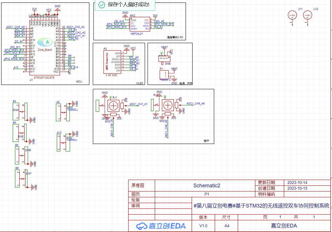
This project uses an STM32 microcontroller as the core, designed using JLCPCB EDA Professional Edition, and downloaded via the ST-Link interface. It uses a plug-in design for easy portability and assembly, and mainly uses a Bluetooth module, a 2.4G module, a DC-DC step-down module, and a gyroscope module for communication, supplemented by an LCD screen for information display and debugging. The remote control board has six buttons corresponding to forward, backward, left and right, reverse gear, and forward gear, enabling multiple ways to control the small cars.
The following is a partial schematic diagram:
Vehicle Board:
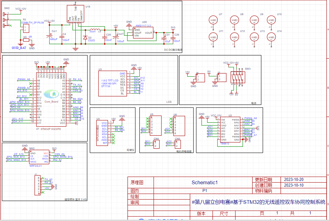
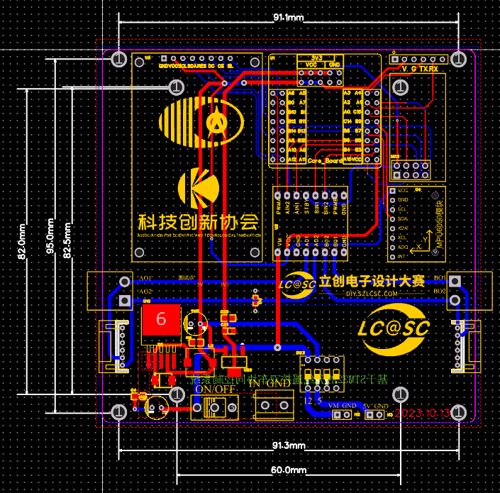
When routing the PCB, pay attention to the distinction between power lines and signal lines, and shield external signals to reduce ripple in the step-down circuit, thus making the 3.3V output more stable.
Remote Control Board:

*5. Software:
This project is mainly developed using Keil5 software in conjunction with the standard library. First, modular programming is performed on each peripheral, and then the logic is written in the main function. The microcontroller HEX file is downloaded via ST-Link.
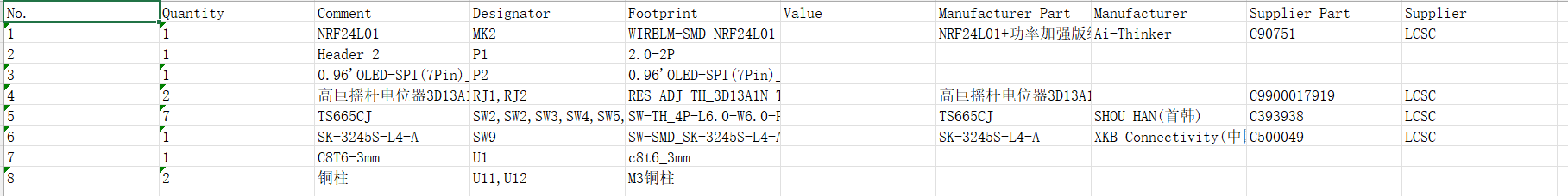
*6. BOM List:
PCB2

PCB4
*7. Competition Logo Verification:

Please upload a project image containing the competition logo. The logo is silkscreened on the PCB.
Click the zip file to download the competition logo! (Competition Logo).zip
*8. Demo your project and record a video.
Video requirements: Please shoot in landscape mode, resolution no less than 1280×720, format Mp4/Mov, single video size limited to 100M;
Video title: LCSC Electronics Competition: {Project Name}-{Video Module Name}; e.g., LCSC Electronics Competition: "Autonomous Driving" - Team Introduction.
More details: https://diy.szlcsc.com/posts/15a52db9fd7d40c492eb505280278e45
9929cf883954c571cbe31fd4548078c8.mp4
9c17a5aaf546d6b20fbd58561dbfc5cb.mp4
PDF_#8th LCSC Electronics Design Contest# Wireless Remote Control Dual-Vehicle Cooperative Control System Based on STM32.zip
Altium_#8th LCSC Electronics Design Contest# Wireless Remote Control Dual-Vehicle Cooperative Control System Based on STM32.zip
PADS_#8th LCSC Electronics Design Contest# Wireless Remote Control Dual-Vehicle Cooperative Control System Based on STM32.zip
BOM_#8th LCSC Electronics Design Contest# Wireless Remote Control Dual-Vehicle Cooperative Control System Based on STM32.xlsx
97487
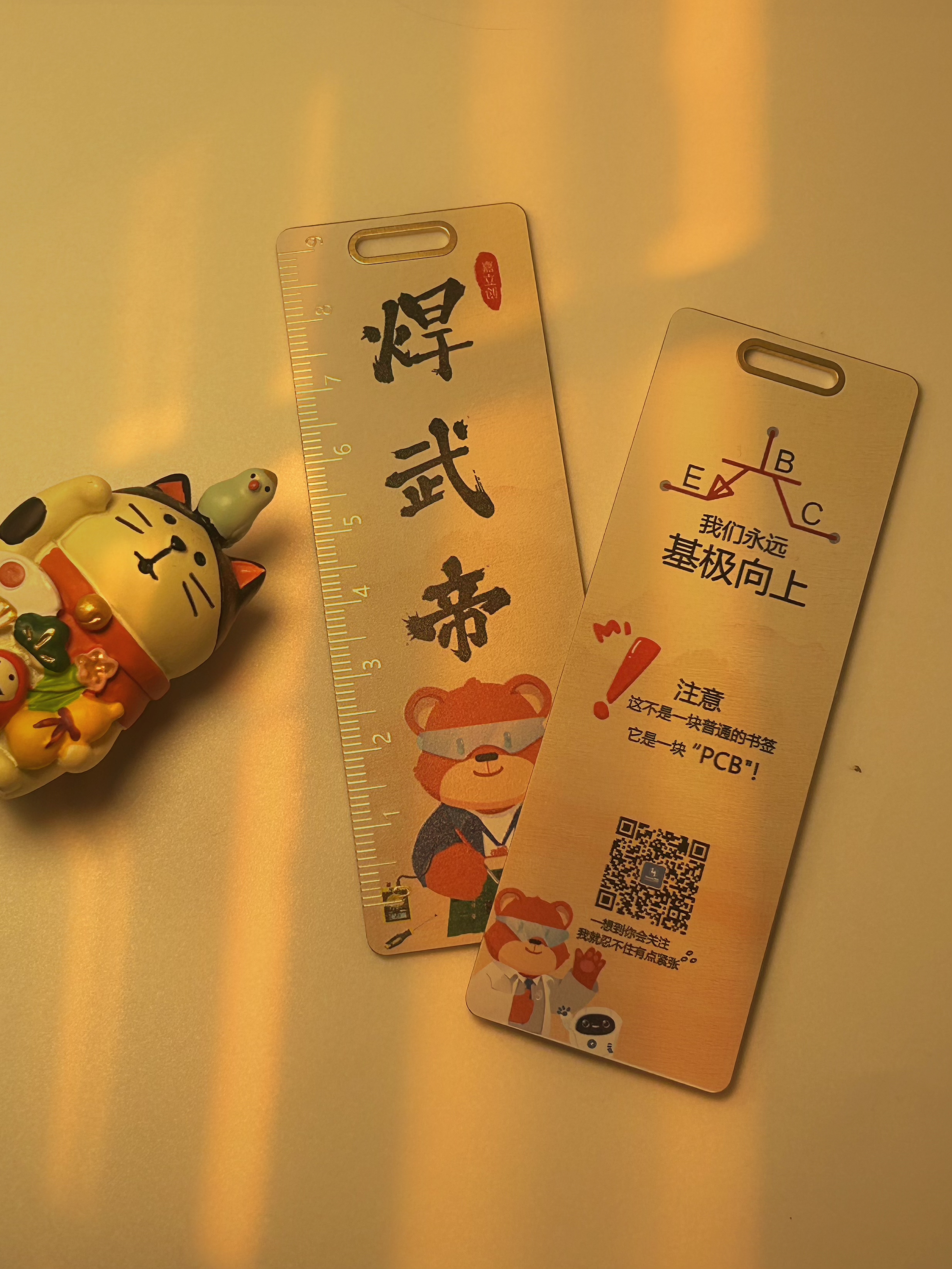
"Welding Emperor" bookmark
Ladies and gentlemen!!! These ruler bookmarks are a must-have for electronics majors!
It would make a great little ruler or electronic craft!
Background.jpg
QR code.png
Stamp.png
exclamation mark.png
Positive and uplifting.png
JLCPCB Little Bear 2.png
Little Bear 3.png
PDF_“Welding Emperor” Bookmarks.zip
Altium_“Welding Emperor” bookmarks.zip
PADS_“Welding Emperor” Bookmarks.zip
BOM_“Welding Emperor” Bookmarks.xlsx
97490
Buck DC-DC Converter - Based on SCT2450 Chip
This product is a DC-DC power supply based on the SCT2450 chip, which is suitable for various high-voltage to low-voltage conversion applications. It is also being used in intelligent vehicle competitions, and the actual test results show stable performance. Therefore, this step-down module was designed.
Let me explain why I chose this chip.
Before this, I had used many DC-DC step-down chips. Driven by the desire to reduce module size, I used the MP2236G chip. While the MP2236G's input and output voltage range was sufficient, it had a fatal flaw: poor current handling. Instantaneous current overload caused the chip to constantly "blow up" (prone to short circuits). Initially, I didn't know the cause, and several different versions failed to resolve the issue. Due to time constraints and a heavy workload, I chose the SCT2450 chip, which offers a wider input and output voltage range, peak current limiting, overcurrent hiccup protection, overheat shutdown protection, output overvoltage protection, and input undervoltage protection, providing multiple layers of safety for practical applications. In actual testing, it worked flawlessly, exhibited excellent stability, and provided highly accurate output voltage.
The SCT2450 chip offers several advantages:
an input voltage range of 3.8V to 36V, support for transient overshoot voltages up to 38V, an adjustable switching frequency from 100kHz to 1.1MHz, peak current control mode, a quiescent current of 25μA in sleep mode, peak current limiting and overcurrent hiccup protection, overheat shutdown protection, output overvoltage protection, and input undervoltage protection. It also comes in a standard 8-pin ESOP-8 package with a simple pinout.
Regarding the design,
I consulted the SCT2450 chip datasheet and studied the circuit and resistor values. My specific output voltage is 6.8V, so I located the adjustable resistor. By increasing the resistor value, the output voltage increases. The 75K resistor in the schematic is the adjustable resistor, which can be adjusted according to your desired output voltage.

PDF_Step-Down DC-DC Converter - Based on SCT2450 Chip.zip
Altium step-down DC-DC converter - based on SCT2450 chip.zip
PADS Step-Down DC-DC Converter - Based on SCT2450 Chip.zip
BOM_Step-down DC-DC Converter - Based on SCT2450 Chip.xlsx
97491
MiniPCIe2USB
This adapter card brings out the USB ports on the MiniPCIe interfaces inside some ThinkPad T60/X60 laptops, which can be used to build a Unifying mouse receiver. This has been verified.
ThinkPad T60/X60 machines have an unused MiniPCIe interface that only supports USB, not PCIe, so it can't accommodate NVMe SSDs. Therefore, it's ideal for using it to house a Unifying mouse receiver.
This adapter card brings out the USB port on the MiniPCIe interface.
Logitech mouse online pairing webpage: https://logiwebconnect.com/select-receiver
Detailed article: https://www.ibmnb.com/thread-2040850-1-1.html
PDF_MiniPCIe2USB.zip
Altium_MiniPCIe2USB.zip
PADS_MiniPCIe2USB.zip
BOM_MiniPCIe2USB.xlsx
97492
electronic


 京公网安备 11010802033920号

 15SMV1000


