My initial motivation
stemmed from over ten years of experience in electronics development. During this challenging period of learning and working, I encountered many helpful people, and I wanted to give back to them. Therefore, I've recently shared quite a few technical articles. Recently, someone asked me how to use the ESP8266 and how to control it with STC. I'll take this opportunity to explain how to achieve this process. I'll also use this project to share how to implement a simple smart home control system using the currently popular IoT technology. If you're interested, please follow along. You can also find the complete code explanation and analysis of this project on the STC forum later (I've been a bit busy with work these past few days, so I can only submit it now and improve it gradually later). If there's enough interest, I can guide everyone step-by-step through building their own complete smart home system, starting from setting up the HA server, haha. (By the way, if you want to learn more about STC microcontrollers, you can also join the QQ group: 884047237). The main functions I want to achieve in this
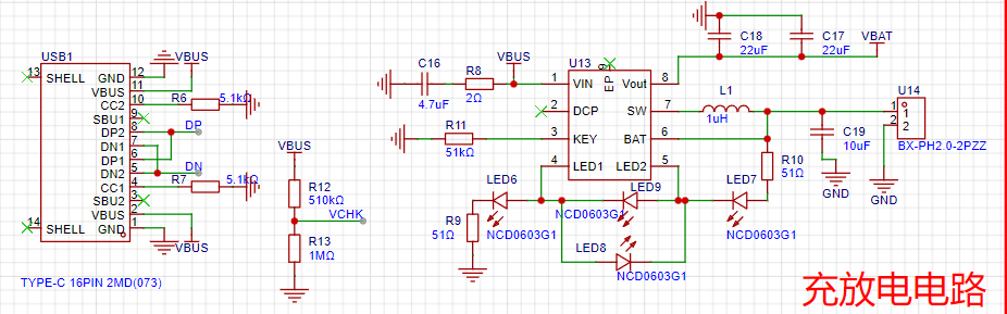
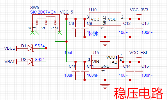
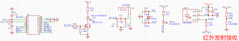
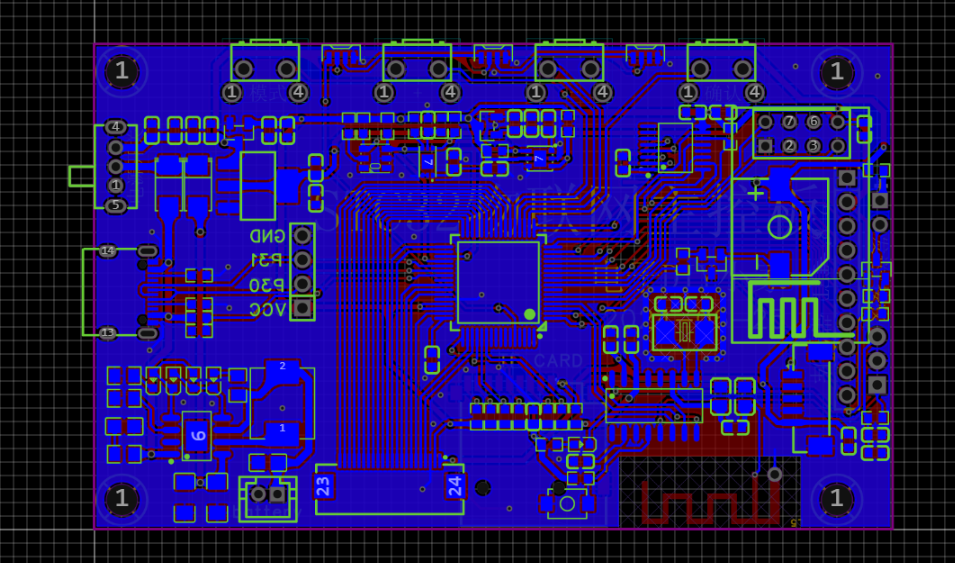
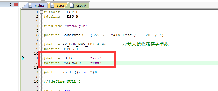
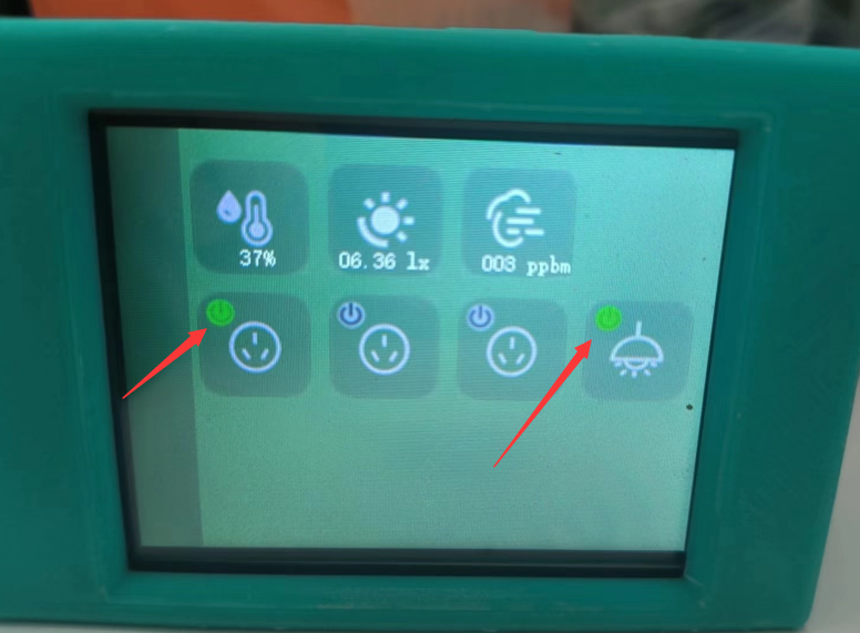
project analysis are as follows: 1. Use the STC32G12K128 as the main controller (after all, this chip is automotive-grade certified! Its performance is excellent), and control the ESP8266 to achieve data interaction with the cloud platform (tentatively Home Assistant; those interested can also build their own Home Assistant platform and play around with it). 2. Acquire temperature and humidity data through temperature and humidity sensors and upload them to the cloud, along with TVOC, CO2, light intensity, and other signals. 3. The cloud can control the local switch signals, and the local device can simultaneously control the remote switch signals. 4. Connect a TFT color screen for simple human-machine interaction; I'm considering a screen with an SPI interface! 5. Port a ZNFAT file system to directly read images from the SD card and display them on the screen. 6. Actually, the board has reserved many other functions, such as infrared transceiver, battery charging, full-color lights, etc., but unfortunately, I have to pay rent soon. I'll buy the accessories and continue testing and improving this post when I have the money. Note: Overall Design Scheme Block Diagram Schematic Design Description 1. Charging and Discharging Circuit This circuit is completely based on the chip's datasheet. Note that there is a VCHK port connected to the MCU for external power input detection. If needed, it can be used to create charging animations or access identifiers. 2. Power Circuit A switch is used to control the main power supply. Since the ESP's wireless transients can reach 500mA, a separate power supply is used to prevent screen or light flickering during communication. 3. Infrared Transmitter and Receiver This is a recently popular integrated infrared transmitter and receiver module. A picture is attached to show it. It has numerous built-in infrared protocols and can update the code library via Bluetooth. Therefore, an antenna is also placed on the board, allowing for direct online code library updates, eliminating the need for self-learning (PS: This chip is a bit expensive; I can't afford it yet, haha, it costs nearly double digits). 4. The Wi-Fi and sensor detection circuits are largely similar. Connect the power supply, then connect the serial communication to the microcontroller's serial port, and the I2C communication to the microcontroller's I2C port. Note that the SGP30 chip is quite delicate; it only requires 1.8V. Therefore, a separate 65K5 power supply is needed. Connecting it directly to 3.3V would likely cause problems, as this chip is more expensive! 5. The touchscreen uses a TFT with a built-in character library. Since the screen itself doesn't have a touchpad, an external touchpad was installed. Because I had a ready-made screen, I didn't replace it. Actually, this system could use a chip without a character library (since the character library can be stored on an SD card), and then find a screen that integrates touch and TFT functionality! Also, although the schematics indicate TSC2046, I soldered XPT2046; I had one on hand, so I didn't buy it, haha, anyway, it's a Pintopin chip. 6. The human body sensor was initially planned to use the Hailing Technology sensor, but due to budget constraints, it's not yet available. Its biggest advantage is its customizable software configuration, allowing adjustment of both detection distance and sensitivity. It's also said to detect both movement and stillness simultaneously (a previous sensor only detected movement, not stillness like sleeping). 7. The STC32 microcontroller currently only has an SPI interface, so SPI is used for reading and writing. The newer STC8051U features 4-wire QSPI, offering faster speeds and better performance. For those requiring high read/write speeds, the latest STC8051U microcontroller is recommended! PCB Design Notes: This PCB is relatively simple, with only a few minor points to note: 1. The infrared chip requires Bluetooth, so copper and traces cannot be run around the Bluetooth antenna; therefore, it's placed at the very edge. 2. Due to the need to consider the casing, the height of the buttons and interfaces must be adjusted to accommodate the board's protrusion. The side Type-C protrudes 1mm from the board edge, and the casing protrudes 2mm from the board edge, ensuring compatibility with most charging cables on the market. The buttons protrude 2mm from the board edge, preventing them from hitting the edge when pressed. Actual testing shows the buttons have a travel of only 0.3mm. Other aspects like cable width and wiring are largely irrelevant; there are no high-speed signals or power supplies here, so as long as the wiring is connected, there's a 99% chance of no problems. The software code is relatively simple, with one .C and one .H file corresponding to each peripheral driver, and a ZNFAT driver ported to another file. The main function is also relatively clear. However, due to time constraints, some user-level code is still somewhat messy. I'll refactor the user-level code after I finish this. Note that those who want to DIY this will need to modify some parts of the code to fully customize it: 1. The Wi-Fi name and password in this file ; 2. The MQTT server username and password in this file. Since my HA is built on a self-assembled NAS, if you're planning to build your own, I recommend buying an HA box, which makes it easy to create a whole-house smart network. Similar to the example below, the biggest advantage of HA is that it can connect to over 90% of smart products on the market, and it can solve the problem of platform incompatibility. For example, Tmall Genie cannot control Mi Home devices, but HA can easily achieve this! If there is enough interest, I will consider making a complete tutorial, starting from scratch and building an HA server to create a complete smart home system. I won't go into detail about the code here; you can download the attachment to see it if needed. Of course, you can leave a message or ask me in the QQ group if you have any questions. I will consider posting a detailed code explanation on the STC forum later. Physical demonstration: The default interface displays the values of 3 sensors, and the displayed content changes every 3 seconds (because temperature and humidity have two parameters, displaying temperature every 3 seconds and humidity every 3 seconds). When the button is turned on, the small green dot next to the icon lights up. Below is the data obtained from the HA server. You can see that both the on/off status and the values are consistent with the local data, thus completely connecting the device and server control. I can use this button to configure and control smart sockets, smart lights, printers, etc. in automation!


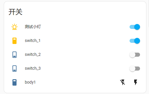

For simple testing, I've configured a very basic rule: whenever the light button on the device is turned on, Xiao Ai (my AI assistant) will announce, "Lights are on!" Doesn't it feel like whole-house smart home technology is within easy reach? All internet-connected devices in your home can be controlled with this little box. **
Important Notes: **
During the DIY process, please pay close attention to electrical and internet safety. Never use it for any illegal or unethical activities.
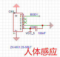
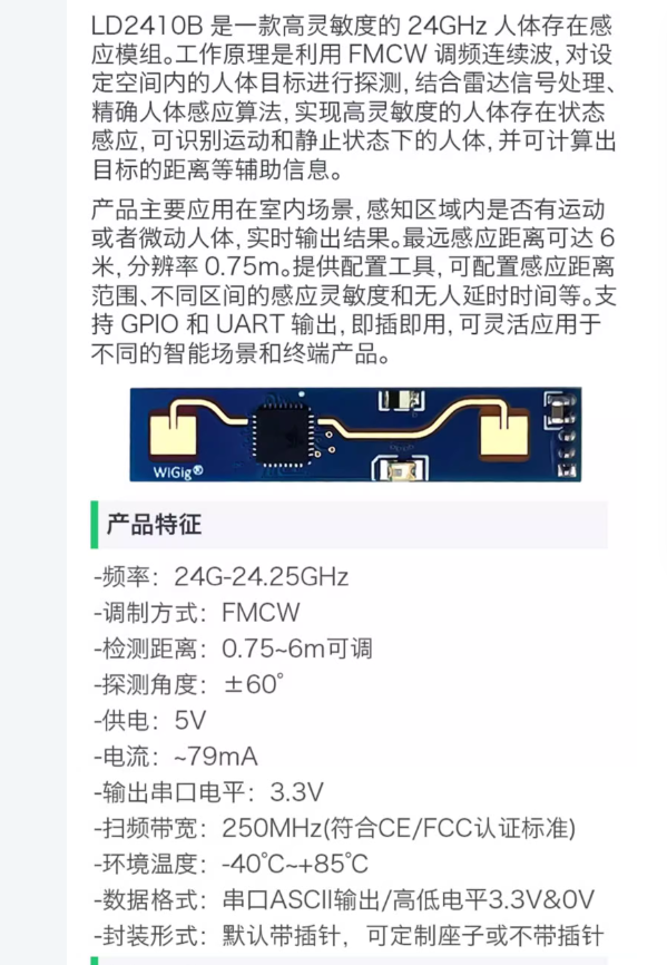
The demo video
will be uploaded later.


 京公网安备 11010802033920号

 WF512K32N-120G4TM5A


