I. Team Introduction
Our team is from Guangdong Transportation Vocational College, and we won the provincial first prize in the 2024 Electronic Design Contest. This open-source project only releases the hardware design scheme; the software source code is not yet open-source.
II. Project Requirements
Design and build a simple blocking recording jamming system (hereinafter referred to as the "jamming system"), including: a recording jamming signal generator (hereinafter referred to as the "signal generator") and an audio signal monitoring/identification module. It should be able to block (selectively block) recording/playback devices and ordinary recording equipment without affecting normal audio communication. The sound generator is responsible for emitting an audio signal with an intensity of normal human conversation sound pressure level (≈50dB/1m), a duration of not less than 10 seconds, and the ability to repeat playback. The recording/playback device can receive, record, and play back audio signals in the frequency range of 100Hz~20kHz, containing storage space sufficient for recording audio signals of ≥10 seconds in length. The sound generator and recording/playback device can be powered by a mobile phone. The working principle block diagram of the shielding system is shown in Figure 1.

III. Design Summary
This design utilizes the nonlinear characteristics of a microphone to create a blocking recording shielding system. It interferes with the sound signal by using a beat frequency signal generated by ultrasonic noise, preventing the recording device from recording. The system first generates a white noise signal using an STM32F405 microcontroller. Then, it filters the white noise using a high-pass filter with a fixed cutoff frequency (25kHz) and a programmable low-pass filter with a settable cutoff frequency, generating a noise signal within a specific frequency range. The amplitude of this noise is then controlled and its power amplified. Finally, it is emitted into the air by an ultrasonic transducer matrix. When the microphone receives this ultrasonic signal, its nonlinear characteristics generate a signal with a large amplitude and a wide sound frequency range, causing the microphone to "block" due to voltage saturation, thus interfering with the normal operation of the recording system.
IV. Problem Analysis
This problem uses ultrasonic transducers. Many ultrasonic transducers are available on the market, including common ultrasonic probes and ultrasonic vibrators. However, how to drive them to operate is crucial. Common solutions using a matrix of ultrasonic probes don't effectively address distance and angle issues, although they can achieve shielding. The shielding effect depends on the number of probes, but this approach is wasteful and generally ineffective. (During a review, I saw a team create a circle filled with ultrasonic probes, but the evaluation results were mediocre). Therefore, this project uses a dedicated 25kHz ultrasonic shield. Below is a more detailed analysis of this task.
Requirement 1: Meeting the shielding distance and angle requirements is sufficient. The distance depends on the distance from which the ultrasonic waves originate, and the angle depends on the placement.
Requirement 2: The simplest approach is to use a microphone, amplify the signal, perform envelope detection, and then use a voltage comparator. Use I/O ports to control LEDs. It's particularly important to use the MAX9814 AGC (Automatic Gauge Control), as audio AGCs offer significant advantages and facilitate later requirements.
Requirement 3: The main issue is programmable power control. For convenient adjustment, a touchscreen is recommended for better visualization.
Requirement 4: Identify and automatically shield different audio segments. Using an audio AGC is one of the best methods here. After collecting and analyzing the FFT data, the frequency of human voices is lower, while the frequency of singing is higher.
V. Overall Design Block Diagram:
The MAX9148 amplifies the signal acquired by the microphone, indicating the presence or absence of sound. The STM32F405 microprocessor is the core of the entire system, primarily digitizing and analyzing the ambient sound signal. It uses its built-in DAC to generate the white noise needed for interference. Users interact with the system via a touchscreen LCD to control the interference system's operation. The MCP41010 digital potentiometer adjusts the amplitude of the interference white noise, thereby adjusting the input power of the interference system. The MAX297, with a fixed cutoff frequency of 20kHz and a programmable cutoff frequency of 20kHz, processes the full-spectrum white noise into narrowband white noise, thus interfering with specific frequency sound signals.

VI. Hardware Circuit Composition
: Power Supply: To provide better stability for the entire solution, a transformer power supply is used. Except for the power amplifier, which has a separate ±15V power supply, all other components use ±5V power.

Sound Acquisition Module: The AGC of the MAX9814 is a purchased integrated module. The MAX9814 features automatic gain control, and the 40dB amplification used in this design is sufficient to meet the design requirements.

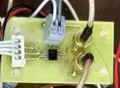
The main controller is a self-designed F405. Due to the need for stable wiring throughout the system, all terminals use KF250 terminals.

The digital potentiometer module MCP41010 allows for programmable resistance adjustment, facilitating control of the white noise output and power control requirements. This module only requires the suggested adapter interface.
Initially, a 20kHz high-pass filter was used, but testing revealed that 25kHz was more suitable, so a fourth-order Butterworth high-pass filter was adopted. This is a voltage-controlled high-pass filter, which better meets the stopband and passband requirements. The
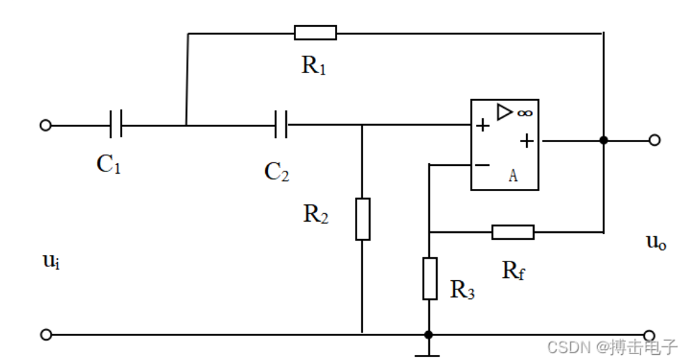
low-pass filter is a MAX297 programmable low-pass filter, an eighth-order low-pass, elliptic function, switched-capacitor filter. Its cutoff frequency can be controlled by a clock. The cutoff frequency is: clock/50. For example, to output a 100kHz square wave signal (the signal needs to be 5V high level and 0V low level), the cutoff frequency is 2kHz. This means that signals with frequencies below 2kHz can pass through our IN port, but frequencies above 2kHz will not pass. The low-pass filter range is between 25-40kHz.

After high-pass and low-pass filtering, the signal is within the desired white noise range (25-40kHz).
Our white noise is then directly amplified by the power amplifier. We are using the LM1875 (actually, Class D amplifiers are more efficient, but we didn't have time to purchase one). This module is readily available; our signal doesn't need excessive amplification, so the power amplifier only needs 11x amplification.

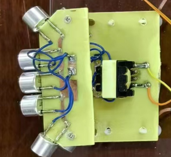
Transducers: We are using 25kHz shielded ultrasonic probes, with 10 probes used, sufficient for the two layers. After amplification, we added a step-up transformer to the board, allowing VPP to reach over 60V, meeting our requirements.
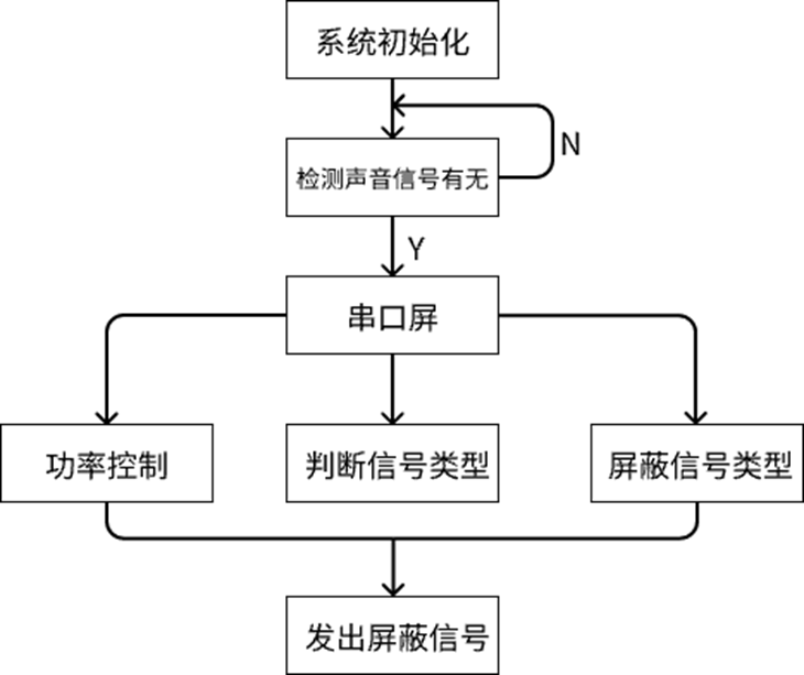
The program flowchart is as follows:
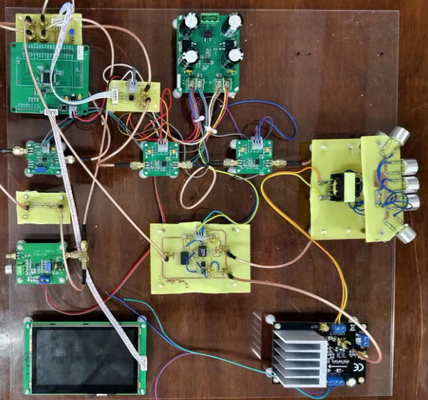
VIII. Physical display
: Acrylic boards and isolation columns are used for secure fixing. SMA connecting cables and KF250 are used extensively. A large number of filter capacitors are added to each board to prevent power supply noise from interfering with the signal. SMA connecting cables are used to make the signal transmission more stable. KF250 terminals can better connect the power lines and will not cause problems such as unreliable power supply.
IX. Actual test results
(1) Measurement results when the output power is 1W
No.
Distance (meters)
Angle (degrees)
Interference result
1
1
60
Success
2
1
90
Success
3
1
120
Success
4
1
180
Unsuccessful
(2) Measurement results when the output power is 2W
No.
Distance (meters)
Angle (degrees)
Interference Result
1
1
60
Success
2
1
90
Success
3
1
120
Success
4
1
180
Unsuccessful
(3) Measurement Result when Output Power is 3W No.
Distance
(meters)
Angle (degrees)
Interference Result
1
1
60
Success
2
1
90
Success
3
1
120
Success
4
1
180
Unsuccessful
(4) Measurement Result when Output Power is 4W
No.
Distance (meters)
Angle (degrees)
Interference Result
1
1.2
60
Success
2
1.2
90
Success
3
1.2
120
Success
4
1.2
180
Unsuccessful
After testing, the maximum interference distance of this design is 2 meters, and the maximum interference angle is 120 degrees.
X. Precautions
Pay attention to the wiring and soldering. Be sure to use SMA connection cable. Traditional DuPont cable is very easy to be loosely connected, causing unstable signal transmission and interference.
XI. Demonstration Video
The video will be uploaded later, as the overall design scheme still needs to be improved.
12.
Currently, only the hardware schematic (PCB) is uploaded as an attachment; the rest is not yet open source.


 京公网安备 11010802033920号

 RA2400


