The preface
was a template provided by JLCPCB, which I filled in directly. Therefore, please don't blame me for any repetitive descriptions or logical errors in the following text. (Disclaimer)
Video Link:
I'm too lazy to upload it to Bilibili, so just check the attachment below.
Project Introduction:
This is a three-channel square wave generator based on STM32 that can generate an adjustable frequency from 1Hz to 8MHz.
(Actually, it's a problem from the 2024 Yanshan University Electronic Engineering Competition Autumn Round. I just finished it and uploaded it; the hardware and code are terrible.)
Project Function:
This design is a PWM generator based on an STM32 microcontroller; it has three separate PWM outputs: a screen and a button panel.
Function: Based on the frequency required by the button output, the output will be automatically activated, and the corresponding PWM will be output automatically.
Project Parameters:
The overall hardware design of the project is not difficult, but the choice of the main control chip was very difficult. High-frequency chips are expensive; cheap chips have low frequencies.
Ultimately, an extremely cheap chip was chosen. If you want to achieve a smaller error in the high-frequency range, you'll have to pay extra!
This design uses the STM32G030F6P6 main control chip, which is small, inexpensive, and has all pins arranged appropriately for the needs. The design uses a 0.96-inch OLED display
with three rows corresponding to three outputs.
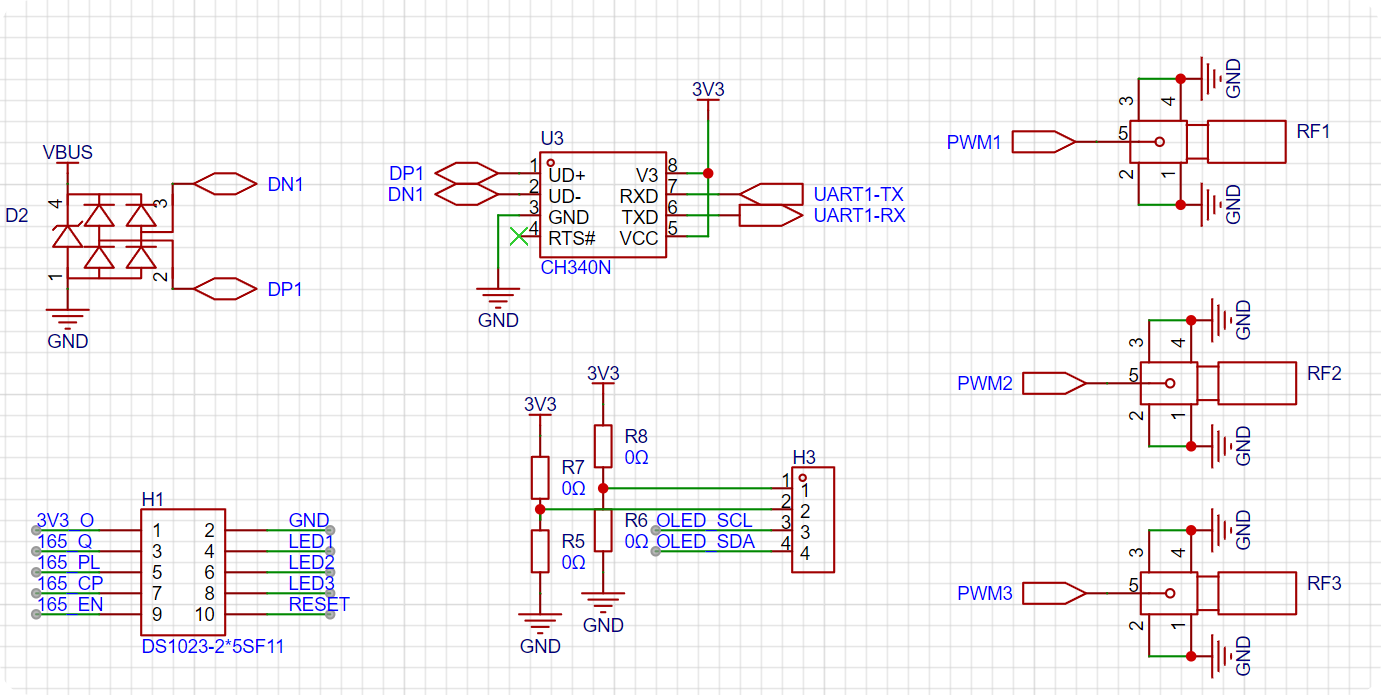
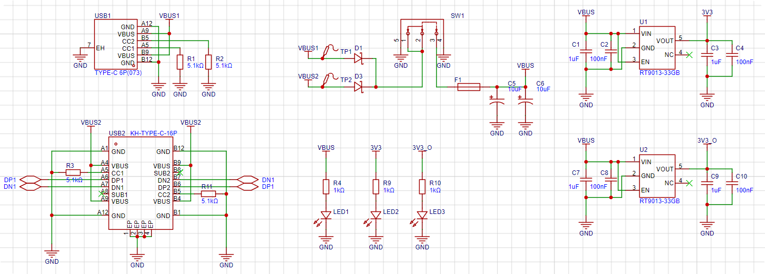
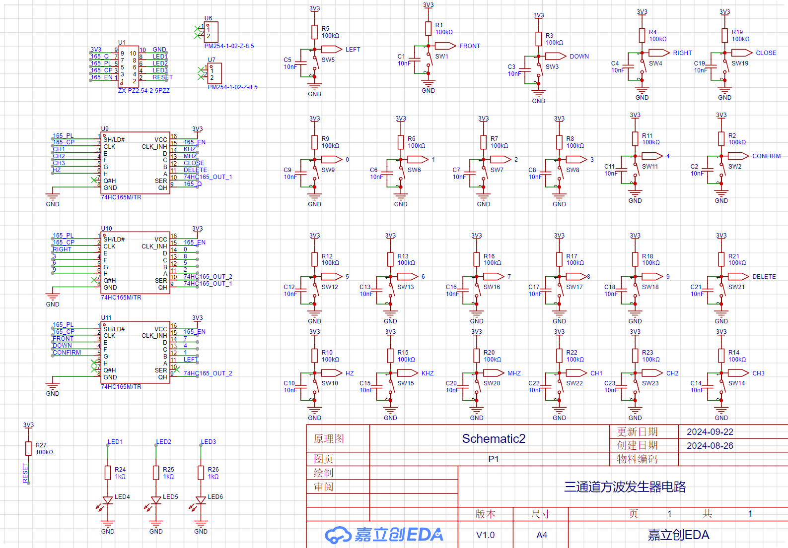
Software calculations are used to obtain the optimal solution for the timer divider and counter while keeping the system clock constant. The project consists of two circuit boards and a purchased 0.96-inch OLED. You can find the 0.96-inch OLED on Taobao (click the blue text to jump). The main control board consists of three parts: the core, peripherals, and power supply. The core part essentially involves the minimum system and pin layout of the STM32G030F6P6. Regarding the pin layout, the peripheral pins are as follows: | Function | Number of Pins | Corresponding Peripheral | Role | | --- | --- |---|---| | Chip Programming Interface | 2 | SWDIO | Programming | | Chip Reset Pin | 1 | NRST | Program Reset | | RF Coaxial Connector | 3 | PWM | Three-channel PWM Output | | 0.96-inch OLED | 2 | I2C | Screen Display | | LED | 3 | GPIO | Indicates whether this port outputs PWM | | Keyboard | 4 | 74HC165 Communication | Keyboard Output | | Serial Port | 2 | USART | Host Computer Communication | Adding two power supply pins, there are exactly 19 pins. The STM32G030F6P6 has a total of 20 pins. Therefore, only one pin is left for an external high-speed crystal oscillator, meaning that the STM32's BYPASS function must be used. Therefore, an active crystal oscillator must be used! Then, a simple test on the STM32CubeMX can help find a suitable pin configuration method. The following is the corresponding circuit diagram. The crystal oscillator section uses a ferrite bead + capacitor filtering scheme to reduce the impact of power supply ripple on crystal oscillator accuracy. Subsequent testing revealed that the actual crystal oscillator frequency accuracy is four decimal places. There are only three programming ports, and the 3V3 power supply pin has been removed. Since it is clear that USB power will be used during programming, there is no power issue. Four M3 screw holes are added for copper pillars to support the overall development board. Two 1*2P female headers are added as structural components connecting the button board and control board. The peripherals involved have already been listed in the main control section above, so they will not be repeated here. The schematic diagram is as follows: The RF head is directly connected to the microcontroller pins without any protection measures. (Because it is directly connected to the oscilloscope during the assessment, it should not be damaged, and this also reduces signal attenuation or delay issues caused by decoupling.) The OLED uses a 1*4P female header, and the power supply port uses a 0402 0Ω resistor as the selection resistor. The pin order of the old and new versions of the 0.96-inch OLED is different; users need to select and solder this according to the purchased module. (Simply solder shorting is sufficient; buying 0Ω resistors is not very meaningful.) The button board has a total of 10 pins: 2 power supply pins, 4 button pins, 3 indicator light pins, and 1 chip reset pin. (This pin is optional, but inconvenient for resetting.) The serial port uses the classic CH340N chip, which is also the most common USB-to-TTL chip. To prevent accidents, a protective TVS diode is added to the differential signal of the USB circuit. The power supply uses two Type-C interfaces as power inputs. After passing through a diode circuit to prevent reverse current flow, the main switch controls the on/off state. A resettable fuse and a power filter capacitor are connected after the main switch to obtain the protected main input power. Since all peripherals use 3V3 as their power supply, the main input power is stepped down to 3V3 through two LDOs. One supply line powers the modules on the main control board, and the other supplies the button array on the button board. The schematic diagram is as follows: USB2 is a 16-pin Type-C connector, which can communicate with the host computer while providing power; USB1 is a 6-pin Type-C connector to prevent power supply to the board if USB2 cannot be soldered. Both USB connectors have 5.1K pull-down resistors on their CC pins for easy identification and configuration by different hosts. Two Schottky diodes, D1 and D3, form a circuit to prevent reverse current flow. When both USB ports are plugged in, the hardware automatically selects the one with the higher voltage as the main power input. (Schottky diodes have lower voltage drop and faster switching speed than ordinary diodes.) F1 is a resettable fuse, which will not malfunction under normal use; it's there to prevent accidental shorting of subsequent circuits during manual soldering. The LDO uses an RT9013-33GB chip, which is small and outputs approximately 500mA, just right for the relatively low current requirements of peripherals. The schematic diagram of the button board is shown below: First, there are 25-pin headers for signal input and 12-pin headers for fixing the structure; this corresponds to the core board. The keyboard module uses cascaded 74HC165 chips; for details, please refer to the video on Huaqiu Mall. The keys use a 10kΩ pull-up resistor and a 10nF capacitor in parallel for hardware debouncing. The LED and chip reset circuits are the basic structure and require no further explanation. (To reset the chip, simply short-circuit the RESET and GND input signals.) The software code is straightforward; everyone has their own coding style, and there's nothing to criticize. This project's code is rewritten based on the HAL library code configured in STM32CubeMX. All written files are located in the Core folder (it's recommended to view them directly in KEIL for a more intuitive understanding).


The modifications I made are as follows (from bottom to top):
| Filename | Function |
| --- | --- |
| oledfont.c | 0.96-inch OLED screen character driver |
| oled.c | 0.96-inch OLED screen display driver |
| 74HC165.c | Keyboard scanning driver |
| pwm.c | PWM output driver |
| oled_opa.c | OLED menu format definition |
| button_opa.c | Button operation function definition | |
menu.c | Menu state machine establishment |
| main.c | Main function |
Notes:
Don't force solder the 16P USB if it won't solder ()
Assembly process
: You still don't know how to assemble it after soldering? ?
Look at the actual picture and you'll understand ()
[Mocking face is stuck in Bengbu]
Actual picture
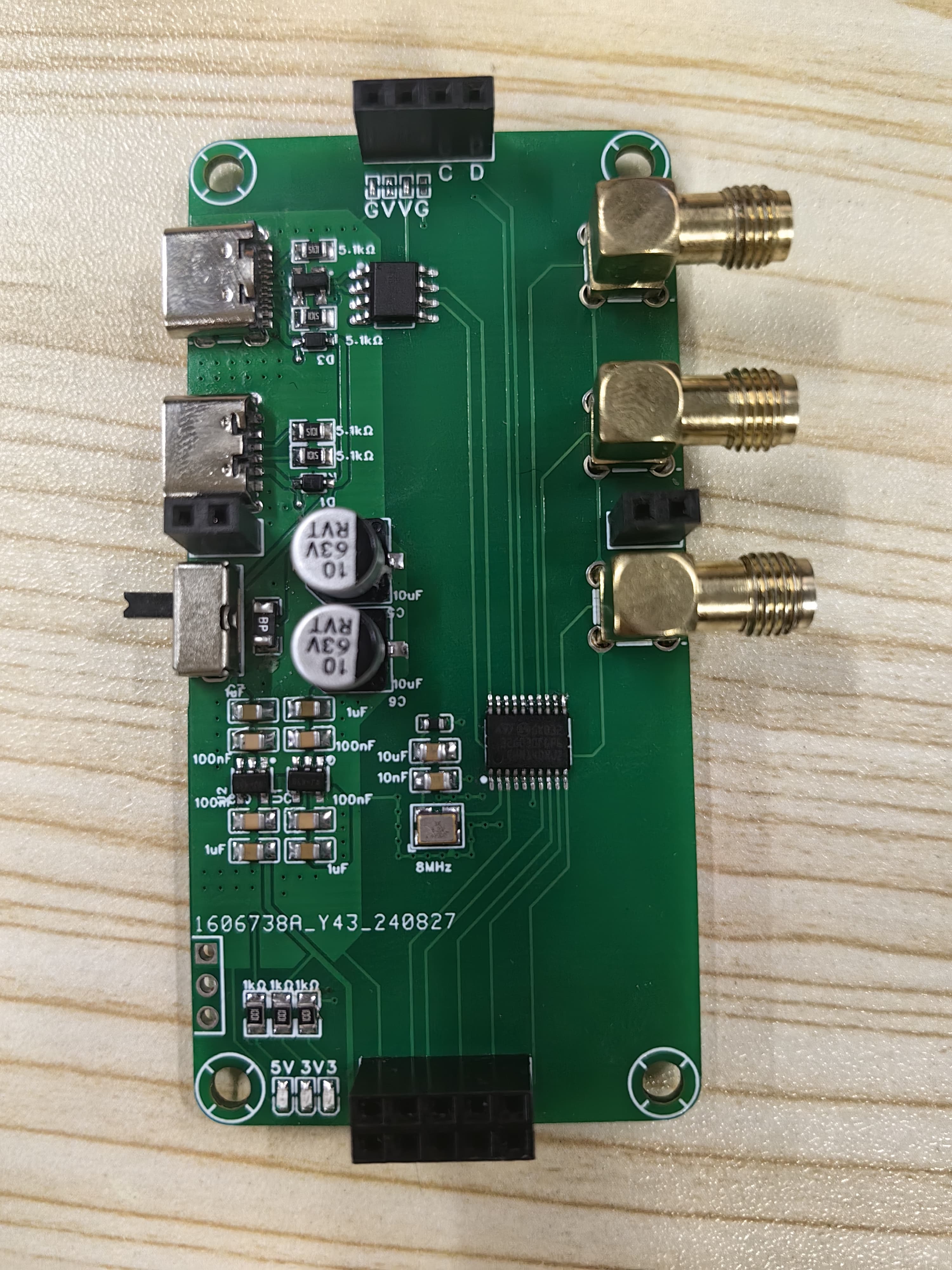
Figure 1: Front view of core board
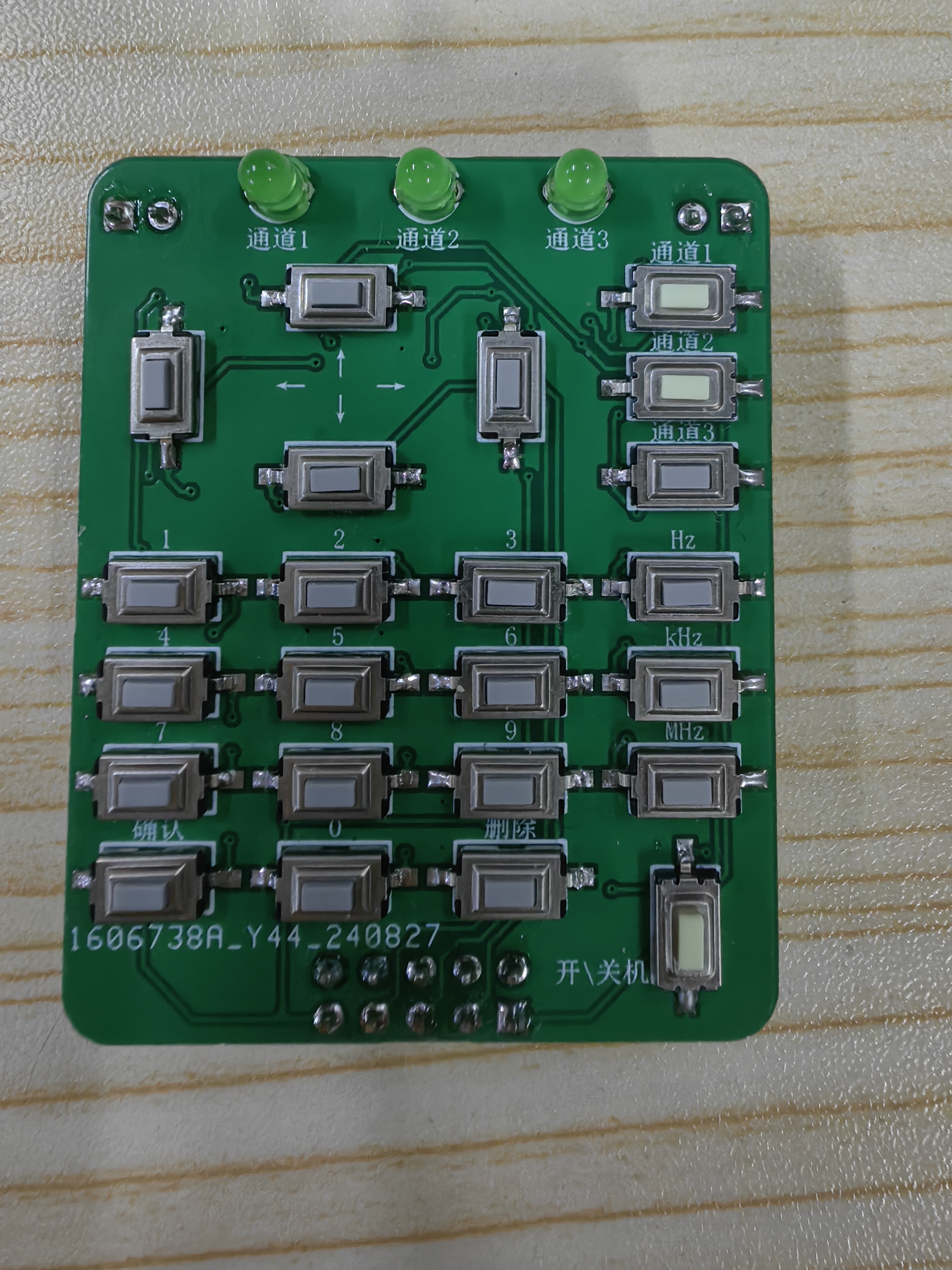
Figure 2: Front view of button board
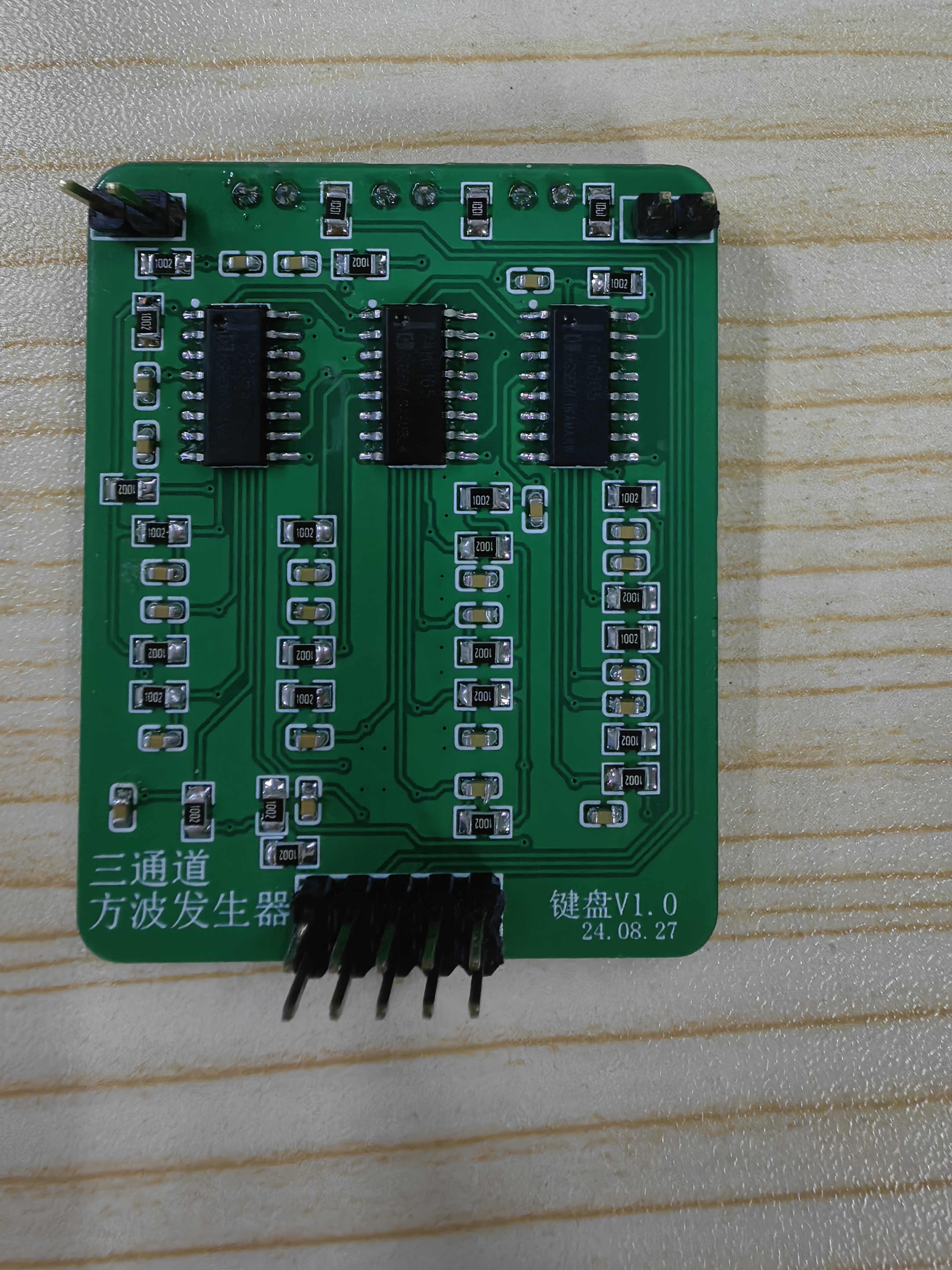
Figure 3: Back view of button board
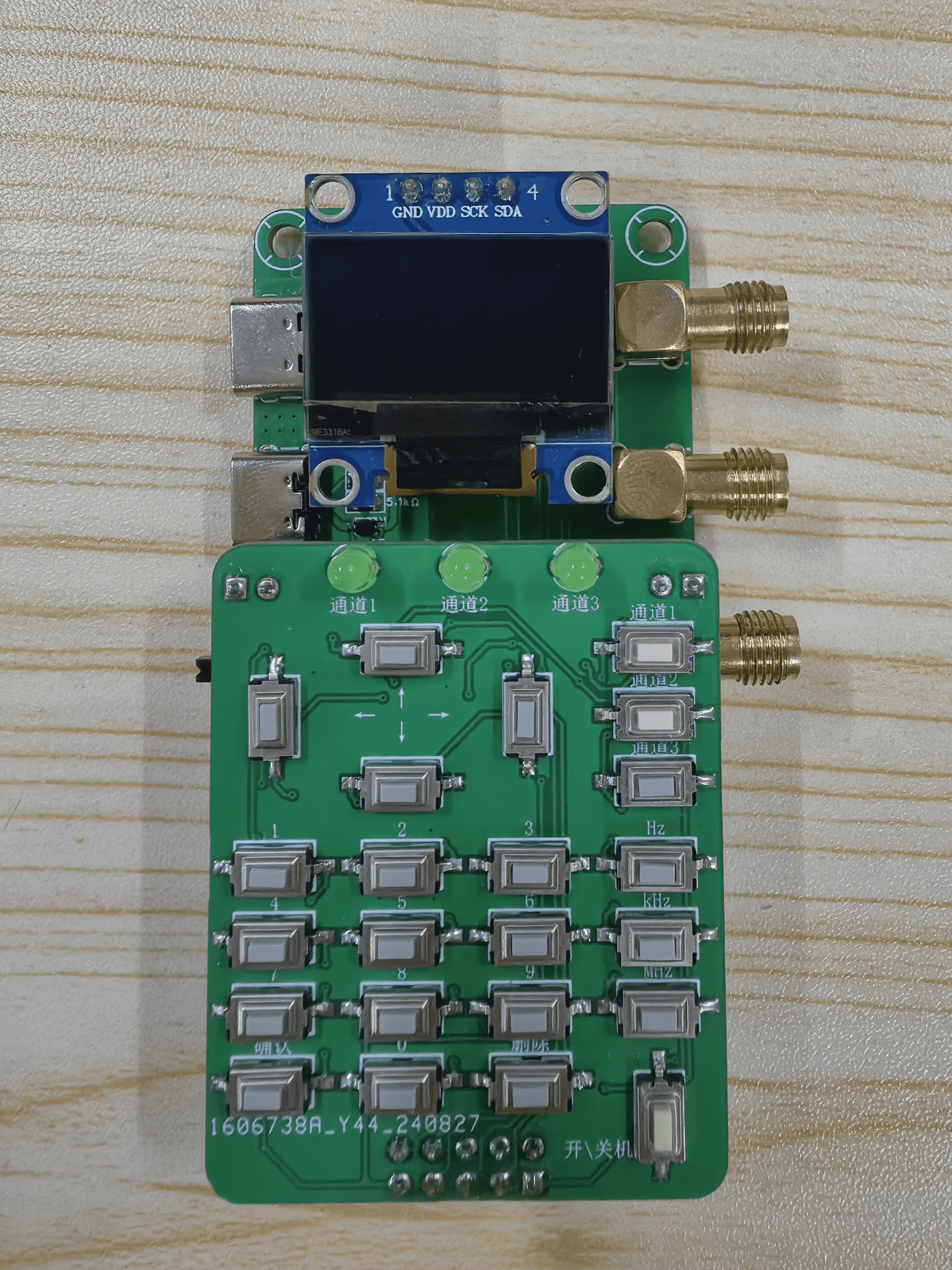
Figure 4: Assembly diagram


 京公网安备 11010802033920号

 1N5230BUR-1TRE3


