Video Link:
Bilibili Video -- Previous Version Outdoor Test Function Demonstration and Introduction;
Latest Version Adds Automatic Search, See Attached Video for Details.
Project Introduction:
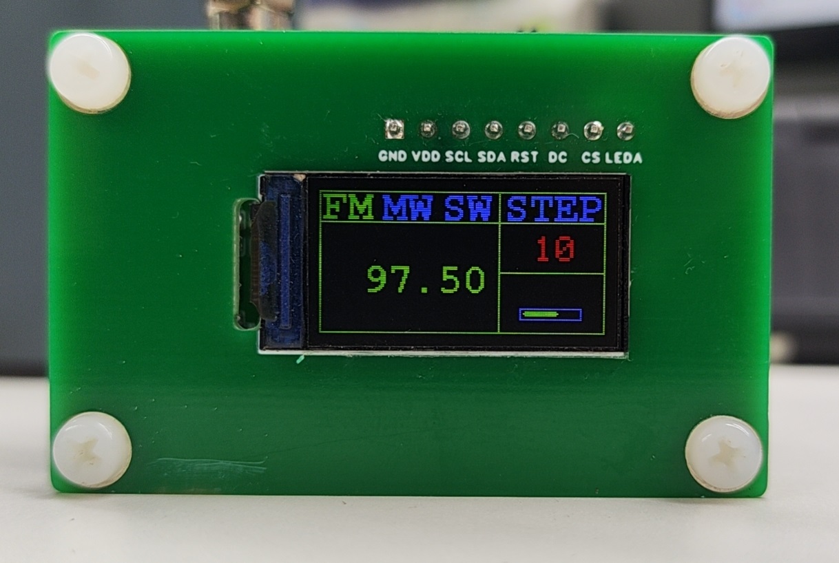
A multi-band radio based on a microcontroller, using a microcontroller (planned to use STM32F103CBT6) and an I2C interface DSP radio chip (planned to use KT0935 or BK1088E) to achieve multi-band radio functionality. Supports AM, shortwave, and FM reception. Supports stereo output, lithium battery charging and power supply, and digital display using an IPS LCD with an SPI interface to display frequency, band, volume, and other information. Antenna Design: Uses a telescopic antenna to receive AM, shortwave, and FM; also supports ferrite coil reception, with reserved interfaces.
Project Functionality
: Supports listening to FM, MW, and SW global bands, using a telescopic antenna; shortwave and AM are suitable for outdoor listening.
Project
Hardware Parameters:
The power switch is a toggle switch;
it has an antenna switch for switching between AM and AM antennas when using a ferrite rod antenna;
7 buttons: 4 on top and 3 on the right. The first and second buttons are for channel tuning, the third for band switching, and the fourth for step adjustment (default step is automatic station selection mode). The first button on the right is volume up, the second is volume down, and the third is screen off;
a 3.5mm headphone jack (does not support external speaker).
The charging interface is Type-C, with a built-in 4054 charging management chip and a built-in 3.0V voltage regulator chip, providing 3.0V core power.
Principle Analysis (Hardware Description):
The STM32F103CBT6 microcontroller controls the screen via the SPI interface and communicates with the radio DSP chip via the I2C interface. The antenna gain is achieved using a 9018 transistor to meet the shortwave reception capability of the short antenna.
...
Software Code:
This project currently only provides firmware, divided into two versions to support 0.96-inch 160*80 IPS color LCD screens from different manufacturers. This series of screens comes in two modes: RGB and BGR. Please select the appropriate firmware mode. The microcontroller model is STM32F103CBT6, compatible with the same series in China.
Note:
This project consists of three boards: a screen board, a microcontroller core board, and a radio chip module board.
For installation, use M3 screw posts with a height of 11mm to ensure proper spacing between layers.
This design does not include a separate casing; a separate board can be placed at the end, with the battery in the middle. Soft-pack batteries or 14500 lithium batteries are recommended. [Image of the actual product]


Firmware.rar
Mini multi-band radio test video.mp4
PDF_Mini Multiband Radio.zip
Altium Mini Multiband Radio.zip
PADS_Mini Multiband Radio.zip
BOM_Mini Multiband Radio.xlsx
92639
ESP Desktop Multifunctional Clock
Multifunctional Clock Based on ESP32S3 Development Board
Function Description:
1. DHT11 Module: Acquires real-time temperature and humidity data (DHT11 accuracy is relatively poor; it should only be used as reference data and should be placed away from the development board and chips).
2. Photoresistor: Uses ESP32 to sample the photoresistor voltage. The screen brightness can be adjusted in the program by setting the duty cycle of the TFT's BL pin based on the sampled value, saving power.
3. Buzzer: Uses a passive electromagnetic buzzer. The I/O port generates PWM to make the buzzer sound and control the volume, realizing an alarm clock function.
4. Buttons: K1 and K2 set the alarm hour and minute; K3: update weather via network; K4: update time via network; K5: stop buzzer sound.
5. After time update, automatically switches between daytime (7-18 PM) and nighttime backgrounds based on the actual time.
6. Uses weather data to display the day's lowest and highest temperatures, and displays four weather icons: sunny, cloudy, overcast, and rainy.
Circuit Description:
1. It's best to design an additional 3.3V LDO module, as relying solely on the development board's LDO will generate significant heat during continuous use.
2. The DHT11 should be kept away from the development board and other chips. During testing, it was found that the DHT11 was significantly affected by the development board's heat, resulting in a large difference between the measured and actual temperatures. 3.
The I/O pins for the K5 button and the development board's LEDs overlap; it's best to select a different I/O pin.
4. An additional 5V LDO power supply has been added, which can be omitted if powered solely by the Type-C port. The added LED is only for functional testing of the 5V LDO circuit and can be omitted.
26dadd8325a3c22bd673e63252ee582e.mp4
PDF_esp Desktop Multifunctional Clock.zip
Altium_esp desktop multi-functional clock.zip
PADS_esp Desktop Multifunctional Clock.zip
BOM_esp Desktop Multifunctional Clock.xlsx
92640
ESP32 Voice Assistant
Similar to Xiao Ai, you can talk to it.
The code requires you to fill in your own Wi-Fi account password, the applied token, your own API Key and Secret Key (iFlytek).
Authentication and music playback both use your own server, and the relevant code is in the server directory.
IMG_0137.mp4
Back view.jpg
PCB Implementation Tutorial.docx
Voice assistant-assisted welding document.html
schematic diagram.png
Actual product image.jpg
SmartAssistant-board.zip
PDF_ESP32 Voice Assistant.zip
Altium_ESP32 Voice Assistant.zip
PADS_ESP32 Voice Assistant.zip
BOM_ESP32 Voice Assistant.xlsx
92641
CW32 Voltmeter and Ammeter Training Camp
The voltage and current meter, made using the LCSC GeoStar-CW32 development board, displays values via a digital tube and uses color silkscreen printing.
Project Overview:
This project uses the LCSC-CW32F030C8T6 development board to build a voltage and current meter. It can detect voltages from 0-30V and currents from 0-3A. Utilizing the CW32 MCU's internal 12-bit high-speed ADC, it achieves high-precision measurements .
I. Principle Analysis (Hardware Description)
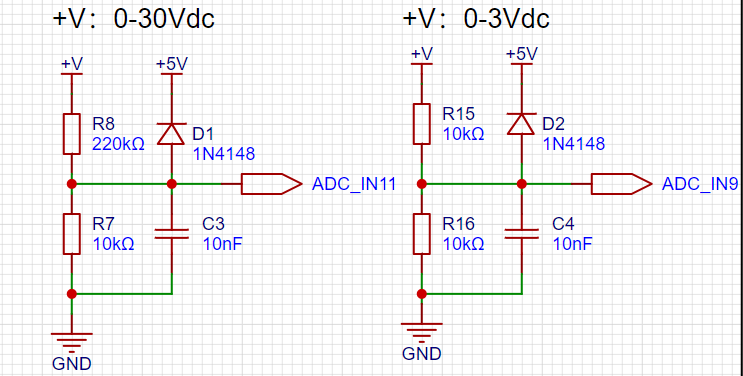
: The voltage acquisition section uses a voltage divider circuit to acquire high voltages. This project supports 30V voltage acquisition, but only the 0-30V range is configured here (for safety reasons, as the safe voltage for the human body is 36V; exceeding this is dangerous). A 1N4148 clamping diode is placed before the ADC measurement to protect the chip from damage caused by excessively high voltage inputs. The 1N4148 clamps the input voltage to 5V, effectively protecting the chip pins. For accurate voltage measurement, two voltage measurement accuracy settings are provided, achieved through different voltage divider resistor settings.
II. Software Code
The software part directly uses the official example without much modification. However, it's important to note that there are some issues to be aware of when setting up and using the CW32 code. The official documentation provides detailed instructions on this (CW32 Digital Voltage and Current Meter Training Camp Project Tutorial Document). You can view the official documentation through this link. Following the official steps should generally resolve any major issues.

III. Physical Object Images
PCB Preview Image Front

PCB Preview Image Color Silkscreen

Display Physical Object

Voltmeter and Ammeter.mp4
PDF_CW32 Voltage and Current Meter Training Camp.zip
Altium_CW32 Voltmeter & Ammeter Training Camp.zip
PADS_CW32 Voltage and Current Meter Training Camp.zip
BOM_CW32 Voltage and Current Meter Training Camp.xlsx
92643
CW32 Voltage and Current Meter
Voltage and current measurement expansion board based on Divinity-CW32F030
Project Overview:
This project originates from the CW32 & LCSC Development Board Voltage and Current Training Camp. It's a voltage and current measurement expansion board implemented using the LCSC CW32F030C8T6 development board.
Features
include: measuring 0~30V voltage and 0~1.5A current;
viewing results via a 3-digit LED display;
voltage or current calibration via buttons to improve measurement accuracy; wide power input
voltage
, which can be shorted with jumpers for analog measurement;
dual-row 3-digit LED display for simultaneous voltage and current measurements;
power indicator and MCU normal operation indicator for accurate measurement;
specific value calibration for more accurate measurements;
Note:
Due to the lack of a regulated power supply, the demonstration used analog measurement with resistor-based voltage division, resulting in some deviation between the measured and actual values.
Functional Test.mp4
PDF_CW32 Voltage and Current Meter.zip
Altium_CW32 voltage and current meter.zip
PADS_CW32 Voltage and Current Meter.zip
BOM_CW32 Voltage and Current Meter.xlsx
92644
electronic


 京公网安备 11010802033920号

 2N6072


