After setting up the hardware, I encountered some minor firmware issues, which took two weeks to resolve.
1. Firmware
: I initially planned to use VIA firmware, but after compiling and flashing it, VIA couldn't connect, and I couldn't find the cause. I had to try Vial firmware, but compilation resulted in an error that the firmware size was too large. Reducing backlight effects resolved the firmware problem.
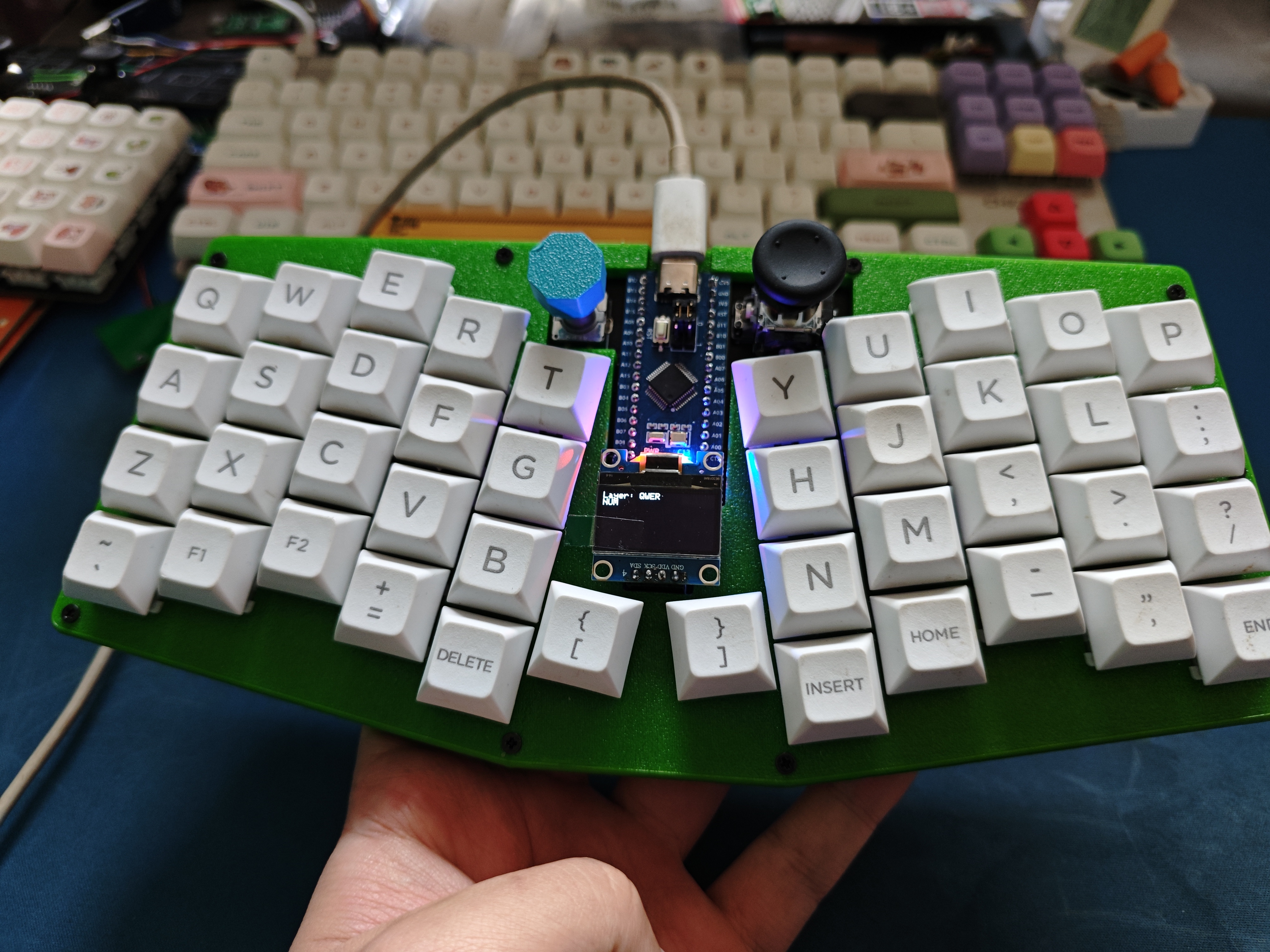
2. OLED Screen:
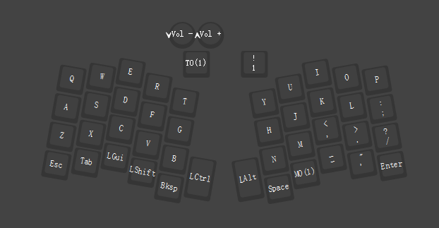
The screen itself wasn't too difficult to work with; I used the official code, which displays button layers and indicator light status.
3. Knob Encoder:
The default layer is volume control; pressing it switches to the second layer. Other layers are undefined.
4. Joystick
: The joystick code wasn't working. I used a pointing device driver, which allows it to be used as a mouse, but the left and right mouse buttons didn't work after being set in Vial, for unknown reasons. It turned out to be a configuration error; the mouse button mapping worked correctly.
5. Hot-
swappable Key Switches: Five-pin switches can be used.
6. RGB Matrix Backlight:
The firmware currently has 14 effects, and the source code has over 40, which can be selected and compiled manually.
It features a customizable keypad and three USB 2.0 ports.
Some computers may only recognize the keyboard keys but not respond to them.
Program burning:
You can directly download my program and follow my tutorial, or you can download the program's compressed package and modify it directly.
Program download tool: http://www.wch.cn/download/WCHISPTool_Setup_exe.html
Download method: Qinheng Microcontroller Code Download_wchisptool 3.2 - CSDN Blog
Program modification method:
Normal keyboard keys:
The keyboard sends 8 bytes of data to the PC each time: BYTE0 BYTE1 BYTE2 BYTE3 BYTE4 BYTE5 BYTE6 BYTE7. The definitions are as follows:
BYTE0 --
|--bit0: Left Control 0x01
|--bit1: Left Shift 0x02
|--bit2: Left Alt 0x04
|--bit3: Left GUI (Win key) 0x08
|--bit4: Right Control 0x10
|--bit5: Right Shift 0x20
|--bit6: Right Alt 0x40
|--bit7: Right GUI 0x80
BYTE1 -- The exact value is unclear; some sources say it's a reserved bit.
BYTE2--BYTE7 -- These six are regular keys.
If you're unsure of the key values, check them here: [Link to online KeyCode Keyboard Key Code Acquisition Tool (jsons.cn)].
Note:
When making the circuit board, the bottom plate doesn't need to be colored; this saves costs and won't affect the display.
The top plate can be adjusted according to your preferred image.
Caution: Be careful
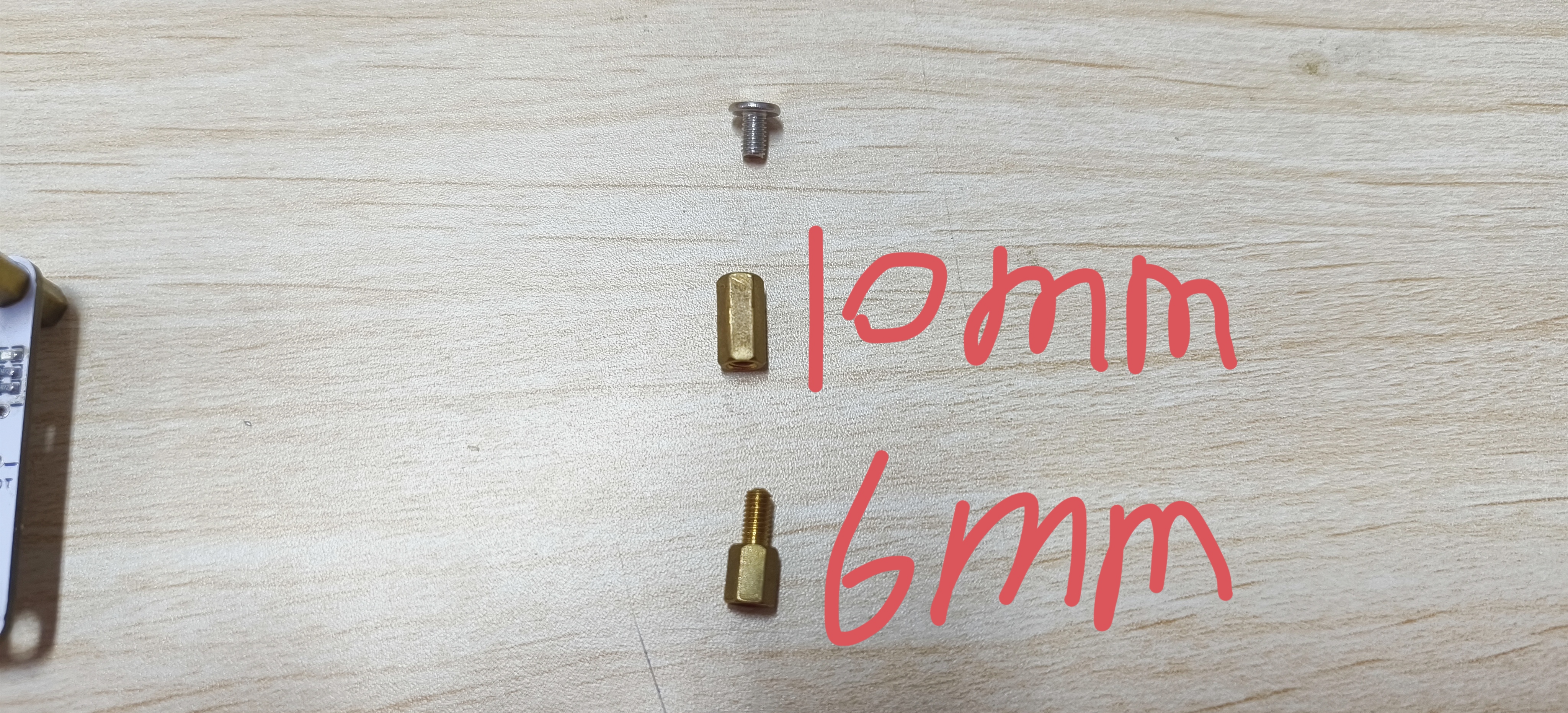
not to buy the wrong components below, otherwise they won't install.
(1) The dimensions of the copper pillar
(2) The surface mount crystal oscillator is 12M, which is not marked on the schematic diagram
(3) Buy a 20mm swivel shank EC11 encoder with 20-bit pulses, like the one below

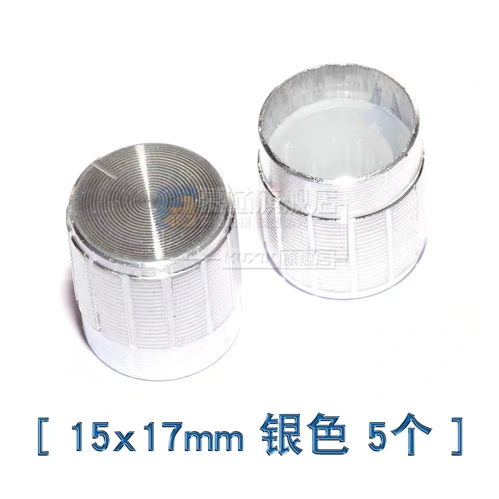
(4) Don't buy the wrong encoder cap either, the one below is just right
(5) Don't solder the BOOT button (only the button is not soldered), otherwise the casing will not be able to be installed after soldering the button. When downloading, just short the two contacts of the button and then power on to recognize it.
(5) When downloading the program, don't select the wrong P3.6 in this part of the software, otherwise it will be troublesome to download the program next time.

Appearance Showcase.mp4
Numeric keypad casing.stl
main.hex
Numpad.zip
Copy and paste to display.mp4
Music Settings.mp4
PDF_Moyu Keyboard.zip
Altium_Slacking Off Keyboard.zip
PADS_Moyu Keyboard.zip
BOM_Moyu Xiaopincai.xlsx
91543
Constant temperature heating table
A constant temperature heating platform based on GD32E230 was developed to realize small-scale semi-automated SMT surface mount welding in dormitories.
Reflow soldering is more convenient, faster, and more efficient than traditional soldering, and it also produces better quality and a more aesthetically pleasing result. The code still needs improvement; I've blown up several optocouplers.
I'm still learning, but I haven't written the program yet. Sigh, I'm still too inexperienced.
This is based on the LCSC development board electronic design call for submissions.
GD32 Constant Temperature Heating Table.zip
PDF_Thermostatic Heating Table.zip
Altium_Thermostatic Heating Table.zip
PADS_Constant Temperature Heating Table.zip
BOM_Constant Temperature Heating Table.xlsx
91545
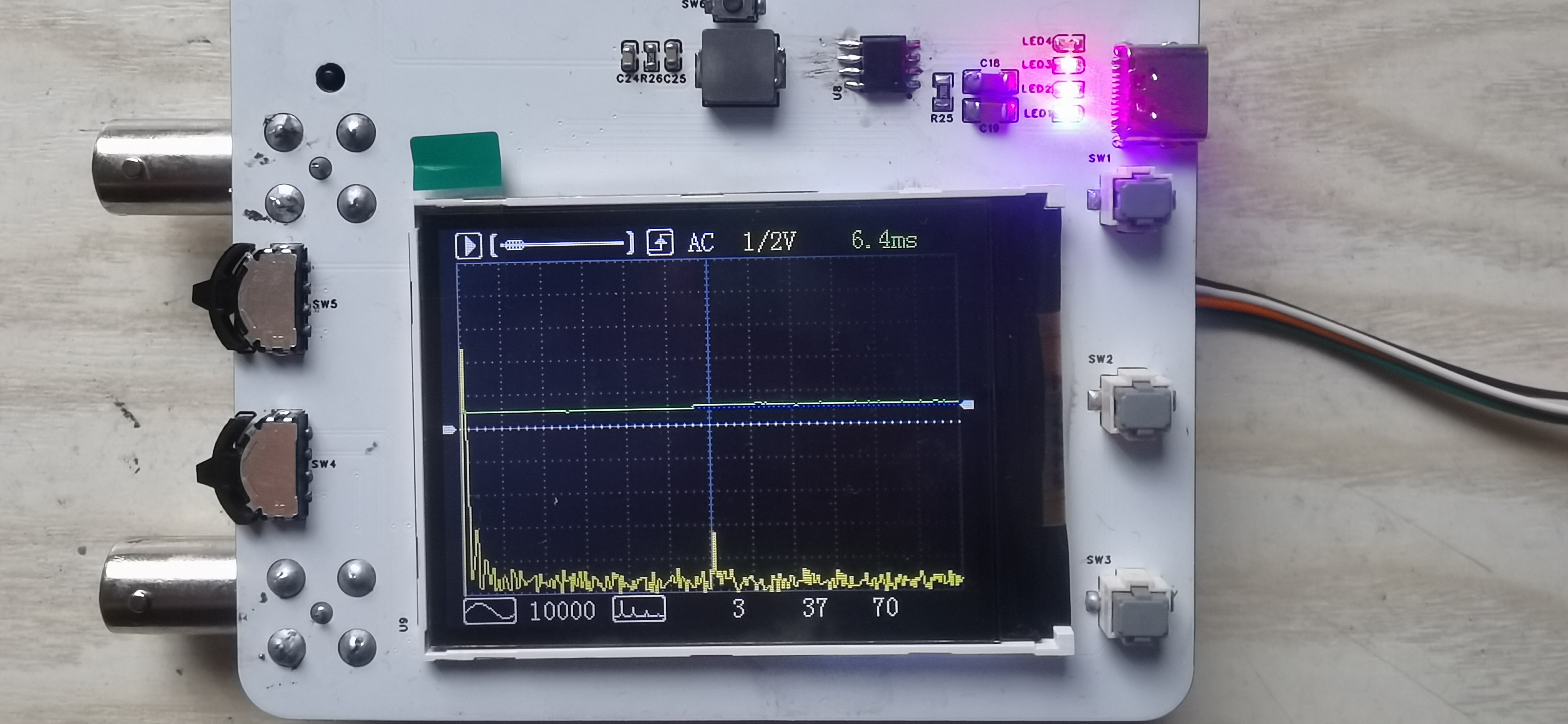
miniature oscilloscope
An oscilloscope is an instrument for observing electrical signals. It displays invisible and intangible electronic signals on a screen, allowing us to intuitively understand and analyze the current operating status of a circuit. Currently, the mainstream oscilloscopes are mainly divided into modal oscilloscopes and digital oscilloscopes.
Oscilloscope Expansion Module Overview
1. Oscilloscope Application Scenarios
An oscilloscope is an instrument for observing electrical signals. It can display electronic signals that are invisible to the naked eye through a screen, allowing us to intuitively understand and analyze the current circuit's operating state. Currently, the mainstream oscilloscopes are mainly divided into analog oscilloscopes and digital oscilloscopes. Analog oscilloscopes mainly process the input electronic signals through operational amplifiers and other means, and then output them directly to the upper and lower bias voltages of the electronic display tube. The waveform is displayed by refreshing in the left and right directions.
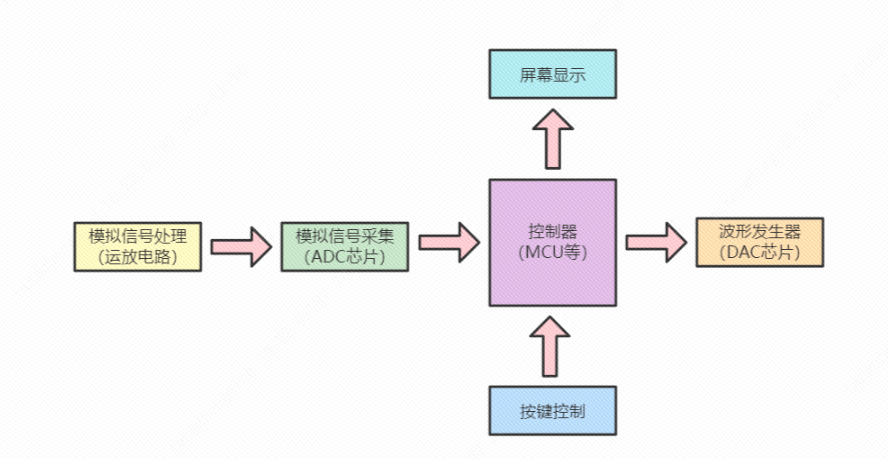
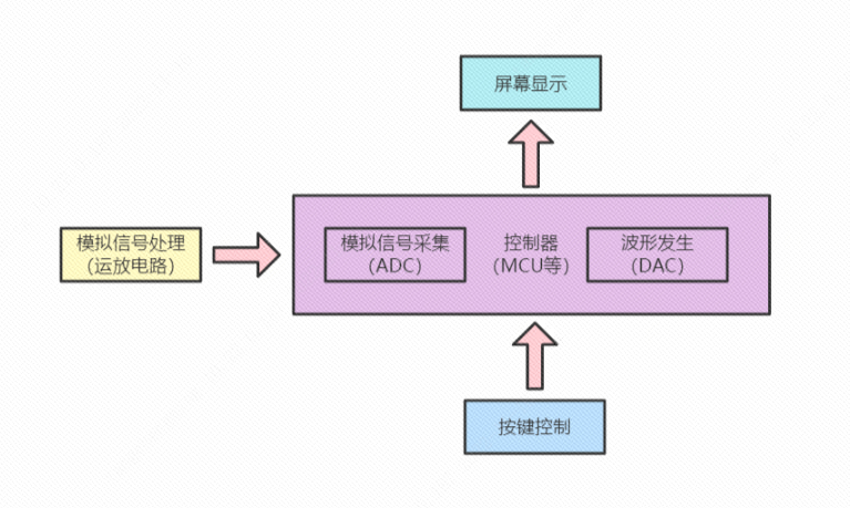
Figure 1-1 Analog Oscilloscope Digital oscilloscopes mainly acquire the processed analog signals through an ADC, and after being processed by a controller, output them to the screen for display. To facilitate analysis and recording, digital oscilloscopes account for a relatively large proportion.
Oscilloscope Expansion Module Overview
1. Oscilloscope Application Scenarios
An oscilloscope is an instrument for observing electrical signals. It can display electronic signals that are invisible to the naked eye through a screen, allowing us to intuitively understand and analyze the current circuit's operating state. Currently, the mainstream oscilloscopes are mainly divided into analog oscilloscopes and digital oscilloscopes. Analog oscilloscopes primarily process input electronic signals through operational amplifiers (op-amps) and output them directly to the upper and lower bias voltages of the cathode ray tube (CRT), creating a waveform display through horizontal refresh. (
Figure 1-1: Analog Oscilloscope) Digital oscilloscopes mainly acquire processed analog signals via an ADC, process them through a controller, and then output them to the screen for display. Digital oscilloscopes are more commonly used for analysis and recording. (

Figure 1-1: Digital Oscilloscope
) 2. The Value of DIY Digital Oscilloscopes
Compared to traditional control circuits, DIY digital oscilloscopes are more challenging, involving analog signal processing (op-amp circuits), analog signal acquisition (ADC), digital signal processing (DSP), screen interface design, waveform generator (DAC), and button function control. DIY oscilloscopes provide a good understanding of analog signal scaling and amplifier usage, digital signal processing capabilities, and microcontroller ADC, DAC, and screen UI design skills. Furthermore, the completed DIY project can be applied to real-world scenarios, which may explain the proliferation of homemade oscilloscopes.
3. Mainstream DIY Oscilloscope Solutions
Currently, the author mainly categorizes existing DIY oscilloscopes online into three types: (This classification may be somewhat biased; please refer to your own understanding.)
The first type is the professional oscilloscope: primarily using RAM as the main controller, FPGA + high-speed ADC chip for analog signal acquisition, high-speed DAC as the waveform generator, and high-precision operational amplifier preamplifier circuitry.

The second type is the practical oscilloscope: primarily using a microcontroller as the main controller, high-speed ADC for analog signal acquisition, high-speed DAC as the waveform generator, and operational amplifier control preamplifier circuitry.
The third type is the learning oscilloscope: primarily using a microcontroller as the main controller, built-in ADC for analog signal acquisition, and simple operational amplifier preamplifier circuitry.
4. Key Highlights of the Liangshanpai Development Board Oscilloscope Module
4.1 Compact and Convenient, Putting the Tool in Your Pocket
4.2 Highly Developed Software Framework, Learning Advanced Development Techniques


4.3 Simple Circuit Design, Quick Start The DIY oscilloscope
adopts a learning-level oscilloscope design scheme, using the built-in ADC and DAC of the Liangshanpai GD32F450 to create a DIY oscilloscope. (The analog circuit design incorporates deep learning and references Anfulai's open-source oscilloscope module circuits, and a usage license has been obtained from Anfulai.)
5. The Liangshanpai development board oscilloscope module features
fully open-source hardware and software functionality, allowing for free definition of more interesting functions.
Sampling Start/Stop: Starts and stops the ADC trigger timer; when paused, detailed information such as maximum and minimum values can be viewed.
Buffer Scroll Bar: Displays the acquisition status by calculating the waveform trigger position; the paused status is displayed by adjusting the offset position.
Rising/Falling Edge: Determines and displays the position when the sampled value and trigger condition are met through software comparison.
AC/DC: Controls the on/off state of the oscilloscope's pre-amplifier coupling relay via IO.
Voltage Scale: Assigns voltage values in 1/2V/div increments; controls the operational amplifier multiplier via IO using an analog switch.
Time Scale: Changes the sampling time scale by controlling the ADC trigger timer period.
Trigger Amplitude: Sets the trigger value and draws the horizontal beam position using software; indicated by a blue dashed line.
Waveform Offset: Shifts the display position vertically using software processing; indicated by a white dashed line.
Waveform display: Instead of the traditional two-point slope line calculation (neither X nor Y coordinates are used), it uses only vertical lines drawn between adjacent points, reducing the amount of code computation.
Waveform generator type: Change the single-cycle data in the DAC's buffer to automatically generate the corresponding waveform output.
Waveform generator frequency: Change the DAC's Time trigger period to automatically generate the corresponding waveform period.
FFT measurement switch: Software controls the display of the FFT spectrum waveform.
FFT frequency measurement: Calculate the frequency using the maximum frequency percentage point, which may differ slightly from the actual frequency.
FFT spectrum scaling factor: Scale the maximum value based on the value that needs to be displayed at a height of 150 pixels.
Display coordinate offset: The sampling state displays the trigger position value, and the paused state displays the manual offset position.
6. Advanced oscilloscope module of Liangshanpai development board:
Since the software framework uses Time+DMA for both ADC and DAC, if an external ADC and DAC are used for advanced development, the Time+DMA data interaction needs to be switched to the corresponding GPIO.
When using DMA+GPIO, it is necessary to use consecutive GPIOs and prevent accidental operation of GPIOs on the same bus (8/16 bits).
PDF_Miniature Oscilloscope.zip
Altium_MiniatureOscilloscope.zip
PADS_Miniature Oscilloscope.zip
BOM_Miniature Oscilloscope.xlsx
91548
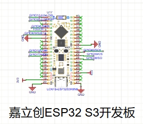
Heating platform controller based on LCSC ESP32 S3 development board
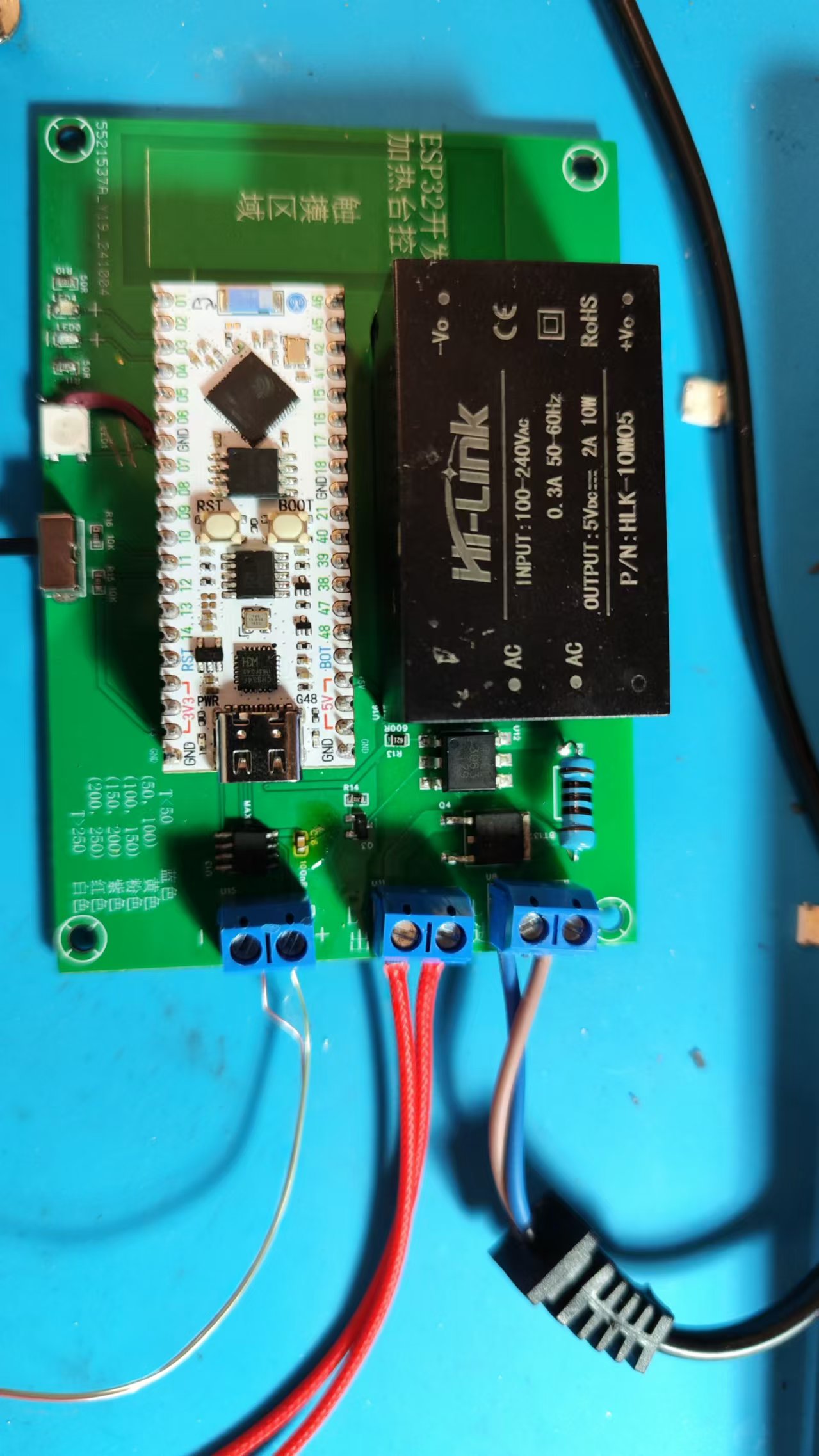
This project uses the JLCPCB ESP32 S3 development board to create a simple controller for a heating plate, allowing it to operate in two phases: low temperature for melting solder paste and high temperature for soldering. A WS2812 microcontroller is used to monitor the heating plate temperature in real time.
I. Project Description
This project, based on the LCSC ESP32-S3 development board, created a simple controller for a heating plate, allowing it to operate in two phases: low temperature for melting solder paste and high temperature for soldering. A WS2812 microcontroller is used to monitor the heating plate temperature in real time.
II. Schematic Design Description
The power supply section
uses an HLK 220V to 5V module.

The main control section uses
the ESP32-S3 development board.
The heating plate control section uses
the ESP32-S3 development board's I/O ports connected to NMOS transistors to control optocouplers and SCRs, thus controlling the heating plate's power supply. The
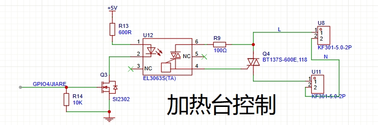
temperature acquisition section
uses a MAX6675 microcontroller with a K-type thermocouple to acquire temperature data . The

switching section
uses a single switch to select between high and low temperature modes.

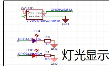
The lighting display
uses two LEDs to indicate the current operating mode: a green LED indicates low temperature mode, and a red LED indicates high temperature mode. A Ws2812b LED displays the current heating plate temperature range: T < 50 (Blue
, 50, 100), Yellow
, 100, 150
, Pink, 150
, 200, Purple, 200, 250);
T > 250 (White )
. The software
uses Arduino programming, and the code is as follows:
#include
#include
#include
#include
#include
#include
#define LED_PIN 6
#define LED_COUNT 1 #define GREEN_LED_PIN
1 #define
RED_LED_PIN
2
#define OUTPUT_PIN 4
#define SWITCH_LOW_PIN 10
#define SWITCH_HIGH_PIN 11 #define SCK_PIN 40 #define
CS_PIN 39
#define SO_PIN 38
Adafruit_NeoPixel strip = Adafruit_NeoPixel(LED_COUNT, LED_PIN, NEO_GRB + NEO_KHZ800);
Thermocouple* thermocouple;
double targetTemperature = 60; // Default target temperature is 60 degrees Celsius
WebServer server(80);
const char* ssid = "XXXXXXXXXXXX";
const char* password = "xxxxxxxxxxxxxx";
// PID parameters
double Kp = 1.5;
double Ki = 0.5;
double Kd = 0.2;
// PID object
double Setpoint, Input, Output;
PID pid(&Input, &Output, &Setpoint, Kp, Ki, Kd, DIRECT);
String temperatureHTML;
void handleRoot() {
double celsius = thermocouple->readCelsius();
temperatureHTML = "";
temperatureHTML += "<h1>Temperature: " + String(celsius) + " C</h1>";
temperatureHTML += "<h1>Target Temperature: " + String(targetTemperature) + " C</h1>";
temperatureHTML += "";
server.send(200, "text/html", temperatureHTML);
}
void handleSetTargetTemperature() {
if (server.hasArg("targetTemp")) {
targetTemperature = server.arg("targetTemp").toDouble();
Setpoint = targetTemperature;
server.send(200, "text/plain", "Target temperature set successfully.");
} else {
server.send(400, "text/plain", "Invalid request.");
}
}
void setup() {
strip.begin();
strip.show();
pinMode(GREEN_LED_PIN, OUTPUT);
pinMode(RED_LED_PIN, OUTPUT);
pinMode(OUTPUT_PIN,OUTPUT);
pinMode(SWITCH_LOW_PIN, INPUT_PULLUP);
pinMode(SWITCH_HIGH_PIN, INPUT_PULLUP);
Serial.begin(9600);
thermocouple = new MAX6675_Thermocouple(SCK_PIN, CS_PIN, SO_PIN);
WiFi.begin(ssid, password);
while (WiFi.status()!= WL_CONNECTED) {
delay(1000);
Serial.println("Connecting to WiFi...");
}
Serial.println("Connected to WiFi.");
server.on("/", handleRoot);
server.on("/setTargetTemperature", handleSetTargetTemperature);
server.begin();
// Set PID parameter
Setpoint = targetTemperature;
pid.SetMode(AUTOMATIC);
}
void loop() {
server.handleClient();
// Check switch status, update target temperature and control logic
if (digitalRead(SWITCH_LOW_PIN) == LOW) {
targetTemperature = 60;
Setpoint = targetTemperature;
// Read thermocouple temperature
Input = thermocouple->readCelsius();
// Run the PID algorithm
pid.Compute();
digitalWrite(OUTPUT_PIN, Output > 0? HIGH : LOW);
} else {
digitalWrite(OUTPUT_PIN, HIGH);
}
// Set the WS2812 color according to the temperature
if (Input < 30) {
strip.setPixelColor(0, strip.Color(0, 0, 255));//blue
} else if (Input >= 30 && Input < 50) {
strip.setPixelColor(0, strip.Color(0, 255, 0));//green
} else if (Input >= 50 && Input < 80) {
strip.setPixelColor(0, strip.Color(255, 255, 0));//yellow
} else if (Input >= 80 && Input < 100) {
strip.setPixelColor(0, strip.Color(255,165,0));//Orange
} else if (Input >= 100 && Input < 170) {
strip.setPixelColor(0, strip.Color(128, 0, 128));//Purple
} else if (Input >= 170 && Input < 220) {
strip.setPixelColor(0, strip.Color(255, 0, 0));//Red
} else if (Input >= 220) {
strip.setPixelColor(0, strip.Color(255, 255, 255));//White
}
strip.show();
// Control the green LED
if (digitalRead(SWITCH_LOW_PIN) == LOW) {
digitalWrite(GREEN_LED_PIN, HIGH);
} else {
digitalWrite(GREEN_LED_PIN, LOW);
}
// Control the red LED
if (digitalRead(SWITCH_HIGH_PIN) == LOW) {
digitalWrite(RED_LED_PIN, HIGH);
} else {
digitalWrite(RED_LED_PIN, LOW);
}
// Update the temperature display on the webpage
handleRoot();
// Output temperature information
Serial.print("Temperature: ");
Serial.print(Input);
Serial.println(" C, Target Temperature: ");
Serial.print(targetTemperature);
Serial.println(" C");
delay(500);
}
IV. Physical Demonstration Instructions

and Precautions
: This project involves high-voltage electricity, please handle with caution!
32d47257958e819700a7dc0980dc0cab.mp4
acedd57667347c4ffd32d2b6b3ae1d17.mp4
PDF_Heating Platform Controller Based on LCSC ESP32 S3 Development Board.zip
Altium-based heating platform controller using LCSC ESP32 S3 development board.zip
PADS Heating Platform Controller Based on LCSC ESP32 S3 Development Board.zip
BOM_Heating Platform Controller Based on LCSC ESP32 S3 Development Board.xlsx
91549
Mini heating table (0402 optimized version)
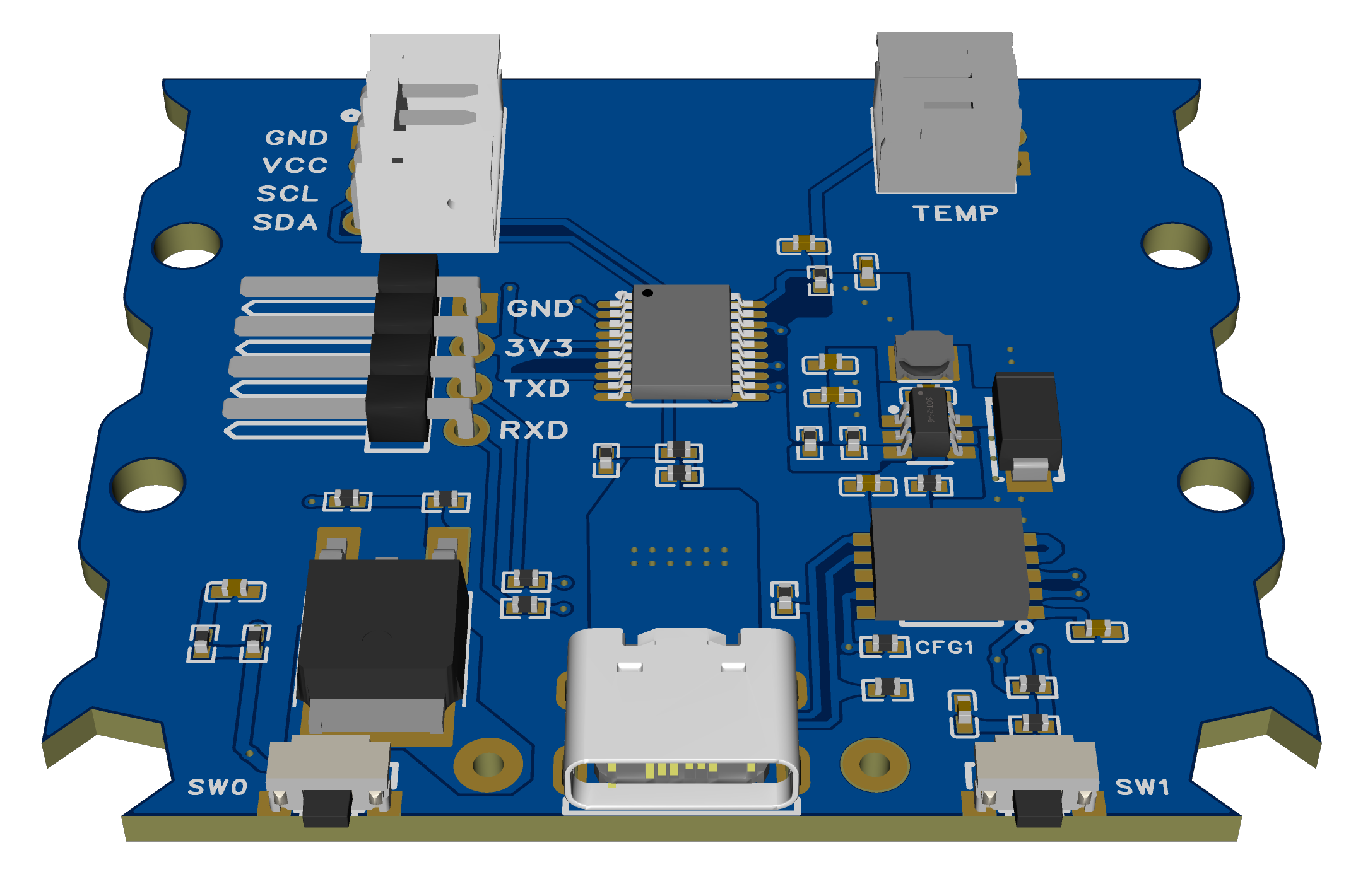
The optimized version of the Little O and Little Q mini heating platform 0402 supports switching decoy voltage and USB download.
This is an optimized version of the O and Q mini heating stages 0402, supporting switching of decoy voltages. Please refer to the original project for assembly and other related information.
The schematic and PCB have been reorganized (for a better look), and the layout of some components has been optimized.
The CH224K's CFG1 configuration pin has been brought out, allowing for configuration of the induced voltage via a resistor (no soldering required, see next item).
All CFG1/CFG2/CFG3 pins of the CH224K are connected to the microcontroller's I/O ports, allowing program-controlled induced voltage.
The 5.1K pull-down resistor pads for CC1 and CC2 have also been retained (the 224K has this resistor built-in and generally does not require soldering).
C6 has been changed from 10uF/25V to 4.7uF/25V, making the 0402 package easier to find (confirmed in the datasheet, does not affect usage).
The screen and temperature sensor use a standard PH2.0 interface for easier socket soldering (wires can also be soldered directly).
The position of the four-pin serial port flashing interface on the board has been adjusted to a 2.54mm header interface for easier wiring.
USB flashing support has been added (software simulation, requires STC-ISP software to install the driver).
Component attributes have been fixed, and all components have been changed to those from LCSC Mall, allowing direct use of the generated BOM.
(Press SW1 ) The button power-on function will switch between 5V/9V/12V/15V/20V to induce voltage (release immediately after power-on, no need to hold down the button). No interface was provided because it's too cumbersome.
Regarding the soldering order (also applicable to the original):
Do not solder the microcontroller and CH224K first. The purpose is to ensure the DC step-down section is working properly. After plugging in the USB port, use a multimeter to measure the voltage between 3V3 and GND to see if it is around 3.3V. Once confirmed, then solder the CH224K and microcontroller.
Otherwise, if the inducer voltage is too high, the step-down output voltage may burn out the CH224K and microcontroller (although theoretically an overvoltage protection circuit could be added to 3.3V, it's not really necessary).
USB flashing method:
Press and hold SW0 to enter USB flashing mode. Then refer to the STC forum posts for software to simulate USB for direct download. STC8/STC32 microcontrollers without hardware USB can also download and install drivers and flash via USB.
(The success rate of USB flashing is not very high in actual testing, the reason is unknown. If you do not want to use it, you can skip soldering the two 22Ω resistors R32 and R33.)
After flashing the firmware for the first time, press and hold the SW1 button to switch the decoy voltage and check if the voltage displayed on the screen changes compared to the last power-on (try several times to see if different voltage levels can be decoyed).
(The modified source code and compiled firmware are provided in the attachment.)
HeatingPlate-PD.hex
code.zip
PDF_mini heating platform (0402 optimized version).zip
Altium_mini Heating Platform (0402 Optimized Version).zip
PADS_mini Heating Table (0402 Optimized Version).zip
BOM_mini heating platform (0402 optimized version).xlsx
91551
PDSink -- Adjustable PD decoy based on CH224K
The PD decoy based on CH224K can adjust the output voltage in real time via a DIP switch.
The PD decoy, based on the CH224K design, allows real-time voltage adjustment via DIP switches, supporting five voltage levels: 5/9/12/15/20V.
It boasts a very compact design, inspired by PDSink modules sold on Taobao (nearly 1:1 replicas; the top image below shows the module purchased from Taobao, and the bottom image shows the module soldered in this project).
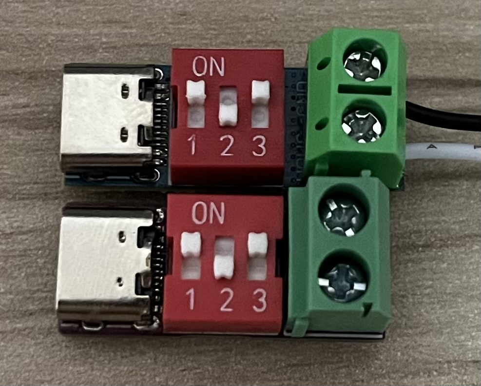

The 1K resistor for VDD power supply uses a 1206 package (consistent with the official verification board), and the copper foil on both the top and bottom layers of the pads is enlarged to enhance heat dissipation (actual heat generation is significantly less than that of the Taobao purchase). Instructions
:
CFG1 corresponds to DIP switch 1;
CFG2 corresponds to DIP switch 2;
CFG3 corresponds to DIP switch 3.
Flipping it down results in 1, and flipping it up results in 0.
A successful decoy will illuminate the LED (if the LED does not light up, check if it is soldered backwards).
Voltage conversion table .

PDF_PDSink -- Adjustable PD decoy based on CH224K.zip
Altium_PDSink -- Adjustable PD decoy based on CH224K.zip
PADS_PDSink -- Adjustable PD decoy based on CH224K.zip
BOM_PDSink -- Adjustable PD decoy based on CH224K.xlsx
91552
Bookmark of Successful Candidates
The PCB bookmark features the phrase "Passing the Imperial Examination with flying colors" before and an "Go for it!" emoji after. Free prototyping is available with a gold-plated prototyping voucher.
The "Top Scholar" bookmark
design is simple yet elegant, with a charming purple background. It symbolizes the wish for high academic achievement and encourages further progress. Though small, the bookmark carries profound meaning, conveying heartfelt blessings. May you find joy in its pages and face the future with greater ease.
It's also a wonderful gift for classmates, conveying heartfelt wishes for a bright future and soaring success.
------------------------------------------------------------------------
Prototyping Method:
Obtain a 2-4 layer immersion gold EDA coupon. The board thickness depends on individual needs.
Choose JLCIC purple for the solder mask color and immersion gold for the pads.
You can purchase tassels (purple is recommended, inexpensive, only a few yuan for nearly a hundred) on Taobao to match the bookmark.
------------------------------------------------------------------------
This is my first time uploading an open-source project. Please point out any problems. Thanks to
JLCIC for providing the free prototyping; without them, this project wouldn't exist.
Some details may not be perfectly executed (but this shouldn't affect the overall design). For better suggestions and ideas, please contact the author via private message at Coolapk@JackZhang06.
------------------------------------------------------------------------
This project references the following open-source projects: This project uses the borders and some designs drawn in
the "Bookmarks - Plum Blossom, Orchid, Bamboo, and Chrysanthemum" project (https://oshwhub.com/2463515595/shu-qian) by OSHWHub@小代 (https://oshwhub.com/2463515595/works). Special thanks are extended to the author for writing the "Top Scholar" message and designing the emoticon (paper version).
PDF_Top of the List Bookmarks.zip
Altium_Top of the List Bookmarks.zip
PADS_Top of the List Bookmarks.zip
91553
electronic
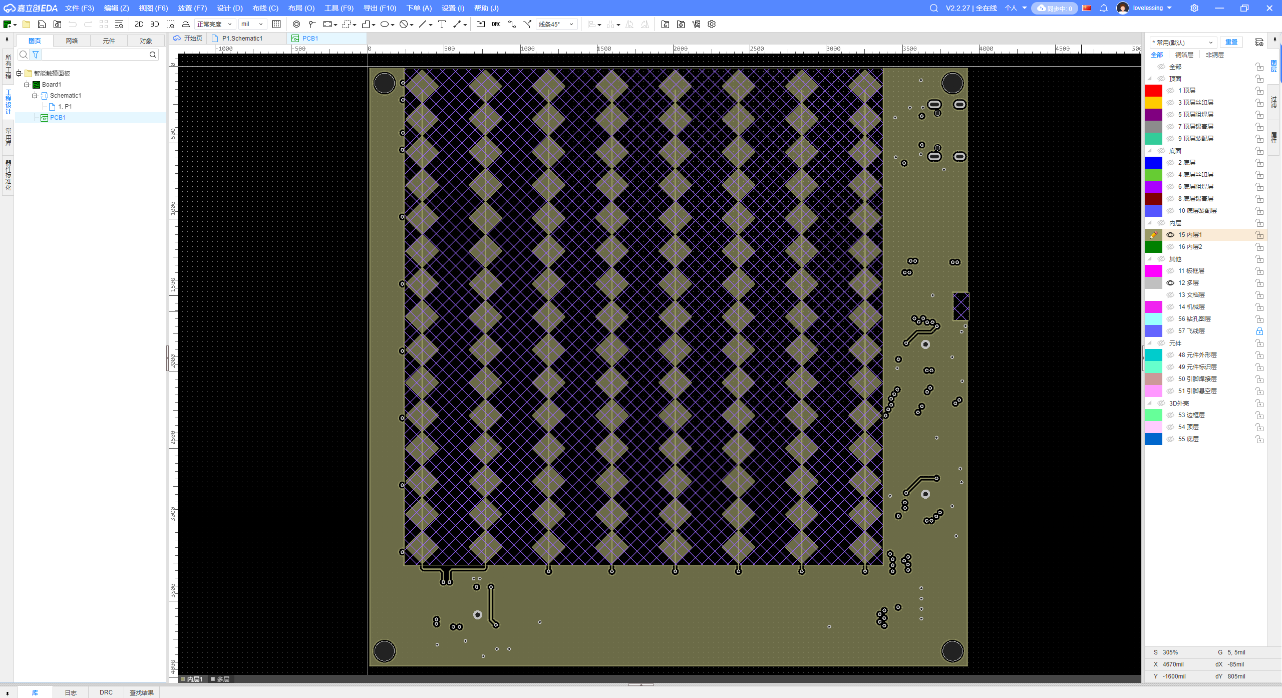 Microcontroller 2 uses 8 capacitance detection pins to measure the capacitance to ground. Inner
  Afterwards, the X and Y axis coordinates are reported separately via serial port and summarized to the master microcontroller, which acts as a USB slave panel device.
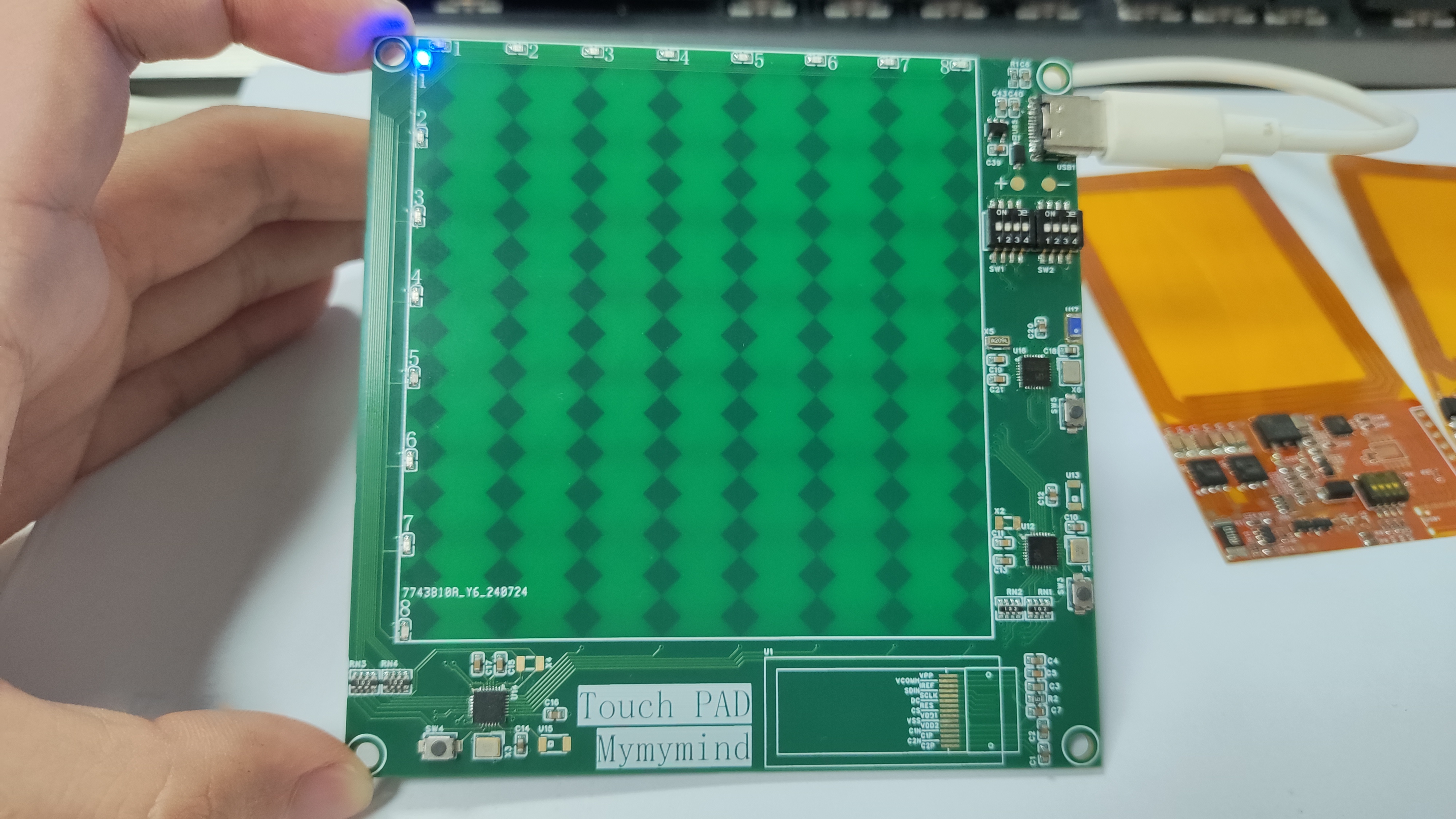


 京公网安备 11010802033920号

 IDT72T3675L6BB


