Bilibili video link [1.1 Introduction to the Experimental Platform] https://www.bilibili.com/video/BV1Rc41147ae/?share_source=copy_web&vd_source=c6c09c8b4011b78d50a8531443528818
[Super Member V4] File shared via Baidu Cloud: Open Source Power Supply Link:

1 Introduction to the Digital Power Supply Platform
1.1 Introduction to the Digital Power Supply Platform Functions
1.1.1 Target Application
For the Electronic Design Contest:
The digital power supply experimental platform makes the verification of the principles of power supply problems in the Electronic Design Contest simpler and more efficient. The experimental platform includes a hardware platform and a software platform. The hardware platform has up to 12 hardware topologies, totaling 16 hardware boards, which can meet the principle verification needs of most solutions. The topology output is stable, and the efficiency, ripple, THD and other parameters of each circuit are excellent. Complete test points are provided to meet debugging needs and ensure debugging safety. The software platform allows for simulation via a graphical interface. Upon successful verification, code is generated with a single click and directly programmed into the corresponding microcontroller for physical verification. The entire process is simple, convenient, and time-saving, allowing even those less experienced in programming to quickly get started. Furthermore, the software and hardware platform supports parallel and cascaded simulation and physical debugging of multiple topologies, making application scenarios more flexible. Operators can also rewrite the code, simplifying physical verification and facilitating the accumulation of programming experience. The platform also provides schematic diagrams for various topologies, enabling operators to learn topology principles and control methods, accumulating hardware knowledge and debugging experience.
For teaching:
Due to its rich variety of topologies, easy code generation, simplified hardware setup process, and powerful parallel and cascaded capabilities and chip compatibility, the digital power supply experimental platform is highly suitable for teaching digital power supply experimental courses. The diverse topologies allow students to learn theoretical knowledge progressively, helping them acquire engineering practice skills and research project experience. The experimental process of first simulating and then implementing the physical prototype, coupled with a stable hardware topology and comprehensive hardware and software protection, significantly improves the success rate of power-on while greatly reducing the risk of hardware burn-out and safety accidents. Complete test points allow students to understand the function and operation of each module; the graphically generated code reduces the difficulty of the experiments and adds much fun to the otherwise tedious programming process.
1.1.2 Advantages of the Experimental Platform:
Safer:
Through a combined virtual and real experimental method, simulation verification is performed first, followed by physical testing. The simulation and physical components correspond one-to-one, reducing trial-and-error costs
and speeding
up the process. Simulation systems and code for single or multiple topologies can be directly generated using an app, and the code can be directly downloaded and burned into the microcontroller.
More Open:
Both the simulation and physical minimum systems are expandable,
and additional functions can be added during multi-topology simulations. Richer:
There are 12 power topologies, covering DC and AC, single-phase and three-phase, isolated and non-isolated. Multiple topologies can be selected for simultaneous cascading and parallel simulation and physical construction.
More Flexible
: Supports microcontrollers under KEIL5 environment such as GD32F470 (domestic microcontroller), TAE32F5300 (domestic microcontroller), STM32F334, G474, and TMS320F28377 under CCS. Automatic generation of
minimum system code; pin compatibility between boards allows for direct replacement of
control algorithm code. Supports C++. Language or graphical interface to meet different design habits
and more interactive
support for graphical code generation with peripherals such as buttons, OLED, and LED, making human-computer interaction more convenient.
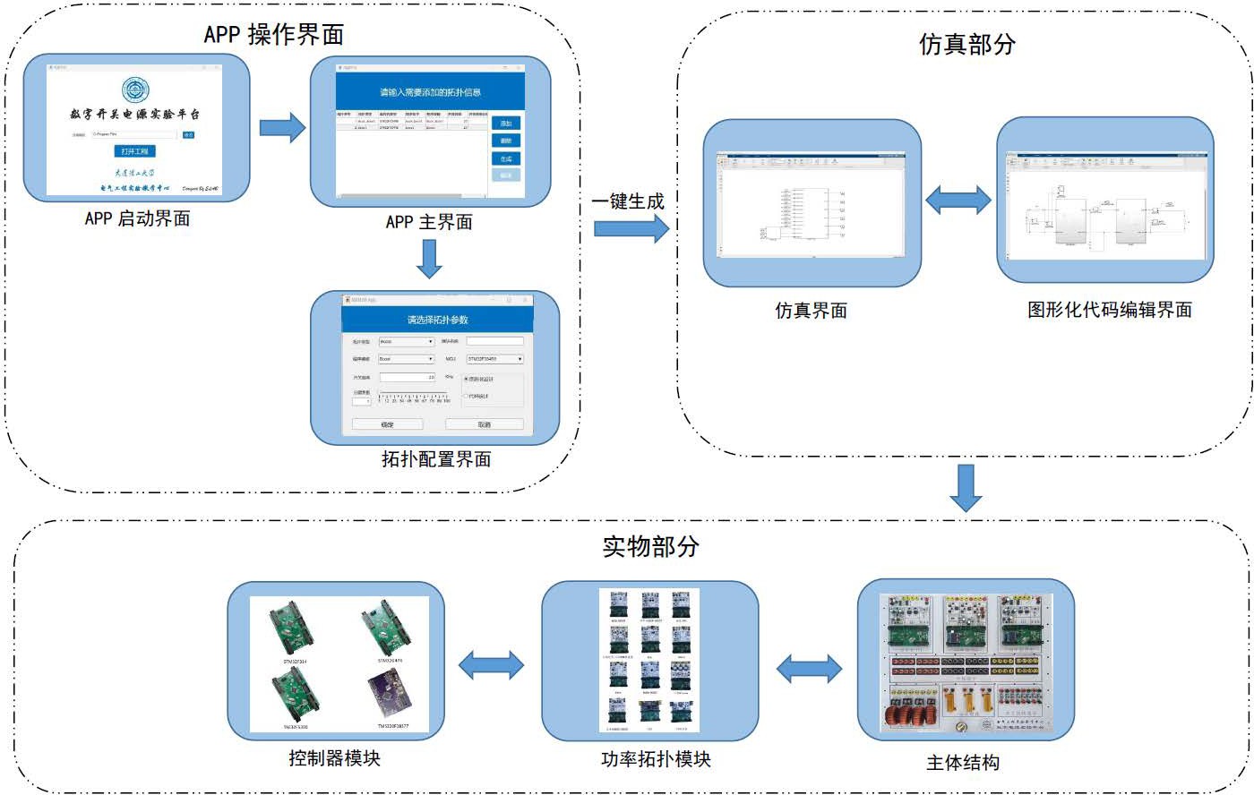
Figure 1.1.1 System Architecture
APP Operation Interface
Startup Interface: Used to select the path to store the project
Main Interface: Used to add/delete topologies, generate projects and code, and compile code
Topology Configuration Interface: Allows selection of topology type, program template, microcontroller model, switching frequency, frequency division factor of control frequency, code programming method, and configuration of module name
Simulation Part
Simulation Interface: Based on the APP The system features automatically generated modules, allowing for parallel and cascaded connections as needed
. A graphical code editing interface is provided, including programming for controller algorithms, buttons, PWM, and ADC. The
main
structure includes three replaceable power topologies, branch terminals, power resistors, inductor terminals, and switch terminals. Power
topology modules include twelve types: buck/boost, buck-boost, inverter/PFC, three-phase inverter/three-phase PWM rectifier, three-phase Vienna, Cuk, Sepic, Zeta, phase-shifted full-bridge, reverse polarity buck-boost, LLC, and gallium nitride, totaling sixteen hardware boards
. Controller modules consist of controllers built from minimum systems such as TAE32F5300 (a domestic microcontroller), STM32F334, STM32G474, and TMS320F28377, with pin compatibility and interchangeability.
(1.1.4 Application

Flowchart; 1.1.2 Application Flowchart;
1.1.5 Product Application Examples
; DC-DC)
Buck single/dual loop control
Boost circuit
Buck-Boost buck-boost circuit
Polarity reversal Buck-boost circuit
Cuk circuit design
Sepic circuit design
Zeta circuit design
LLC soft switching design
Phase-shifted full-bridge design Gallium
nitride high-frequency power supply design SPWM control of
DC-AC
inverter Phase
-locked loop control of inverter
Phase-locked loop control
of three-phase inverter SPWM control of
three-phase inverter SVPWM control of three-phase inverter
ACDC
single-phase power factor correction SPWM control of three-phase
PWM rectifier Two-level SVPWM control of three-phase PWM rectifier Vienna three-level SVPWM control Vienna phase-locked loop control Multi-topology integrated application Bidirectional DC-DC energy storage Three-port MPPT Three-phase microgrid grid- connected single-phase online UPS Three-phase online UPS Three-phase ACDC car charging pile Three-phase energy storage car charging pile load point power supply 1.2 Introduction to Liangshanpai development board resources in digital power supply
In the microcontroller of the experimental platform, we added compatibility with the Liangshanpai GD32F470 series. This mainly utilizes resources such as ADC, advanced timers, I2C, and GPIO. A brief introduction to these is provided below.
1.2.1 Introduction to the GD32's ADC
The GD32F4 uses a successive approximation 12-bit ADC with 19 multiplexed channels. These 19 channels originate from analog signals from 16 external channels, 2 internal channels, and one battery voltage (VBAT) channel. The 16 external channels are obtained through GPIO multiplexing, while the 2 internal channels are the internal temperature sensor and the internal reference voltage, respectively. The battery voltage (VBAT) needs to be connected to the chip's VBAT pin for acquisition. Each of the 16 external channels corresponds to a specific pin on the microcontroller; this pin is not fixed and can be one pin per channel or two pins per channel.
The A/D conversion of each channel can be configured for single-shot, continuous, scan, or intermittent conversion modes.
Single Conversion Mode: After each ADC conversion, the ADC automatically stops and stores the result in the ADC data register.
Continuous Conversion Mode: After completing one conversion, the ADC automatically starts another conversion, continuing until stopped by external or software triggering.
Scan Mode: Used for sequential conversion of multiple input channels. In scan mode, the ADC samples and converts multiple channels sequentially according to the configured channel acquisition order.
Intermittent Mode: Used to switch between injection channels and regular channels. In intermittent mode, the ADC prioritizes converting injection channels; after injection conversion is complete, it automatically switches to regular channels for conversion.
The ADC conversion result can ultimately be stored in a 16-bit data register in a left-aligned or right-aligned manner. This section uses scan mode to achieve single-channel single-acquisition. By setting different acquisition channels, multiple channels can be acquired sequentially in single-acquisition.
1.2.2 Introduction to GD32 Hardware I2C
The GD32F470 has three hardware I2C peripherals, which are internal circuits that allow communication with external I2C interfaces. The hardware I2C module on the GD32F4 chip uses specific pin multiplexing for data and clock signal transmission.
Timing control of the hardware I2C module is implemented by hardware circuits and registers. These circuits and registers are responsible for generating the clock and controlling the level changes of the data lines to conform to the timing requirements of the I2C communication protocol. They can automatically process the timing signals required for I2C communication, ensuring that data transmission occurs on the correct timeline. Through the automatic control of the hardware I2C module, timing control can be more accurate and reliable, thereby improving the success rate of communication.
Hardware I2C also supports interrupts and DMA. It can communicate with the processor via interrupts or DMA. This allows the processor to perform other tasks during data transmission, improving system efficiency and performance.
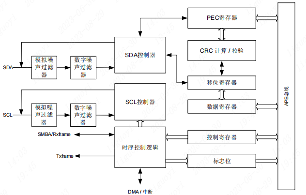
Figure 1.2.1 shows the hardware I2C block diagram.
The hardware I2C module on the GD32F470ZGT6 only supports standard mode (100 kHz) and fast mode (400 kHz) to meet the communication needs of different application scenarios.
1.2.3 Timer Resources of GD32 The
GD32F450ZGT6 has a total of 14 timers, which can be divided into five types: Advanced Timers 0/7, General Purpose Timers (L0) 1-4, General Purpose Timers (L1) 8/11, General Purpose Timers (L2) 9/10/12/13, and Basic Timers 5/6. The number of functions available for each type of timer varies; generally, Advanced Timers have the most functions, followed by General Purpose Timers, and Basic Timers have the fewest. For a detailed comparison of functions, please refer to page 356 of the user manual.
Advanced Timers (TIMER0 and TIMER7) are four-channel timers that support input capture and output comparison. They can generate PWM signals to control motors and manage power. Advanced Timers include a dead-time insertion module, which is very suitable for motor control.
The main characteristics of Advanced Timers are shown in Figure 1.2.2.

Figure 1.2.2 Main Characteristics of Advanced Timers
1.3 Digital Power Supply Platform Functional Testing
Below, we will use the 2021 National Competition three-port example to demonstrate how to use the experimental platform to quickly verify the solution to the real competition problem in ten minutes.
The first step is to create a new folder for subsequent code and simulation. Select the newly created folder on the main interface of the app.
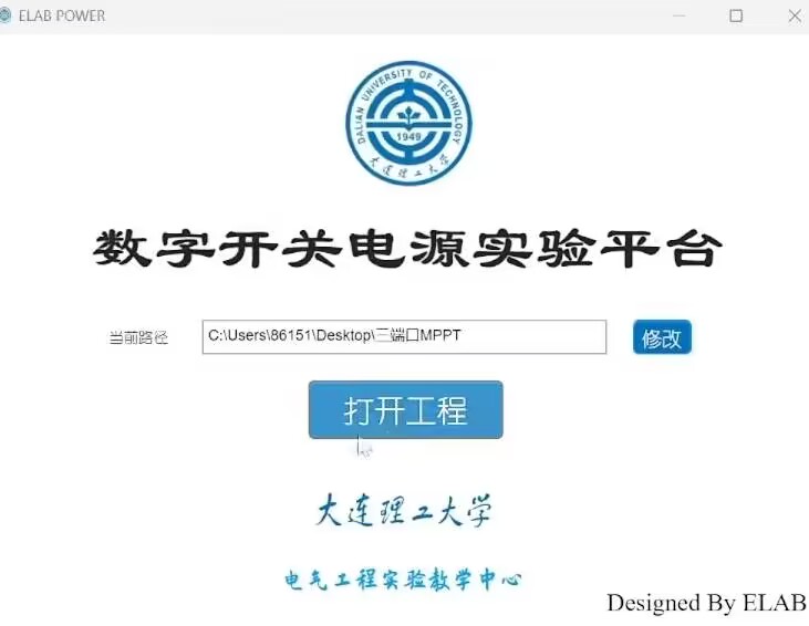
(Figure 1.3.1: Creating a new folder)
The second step is to select the required topology for the solution. The first topology is the BUCK-BOOST circuit, controlled by an STM32F334 microcontroller minimum system, and programmed using a graphical interface. The second topology is the BOOST circuit, controlled by a TAE32 microcontroller minimum system, also programmed using a graphical interface.

(Figure 1.3.2: Selecting a topology)
The third step is to generate the project with one click and wait for the files to be generated. In Simulink, connect the two topologies according to the requirements of the problem. Connect a 10-ohm resistor to the voltage source to simulate the internal resistance of the photovoltaic panel, and then connect the BUCK-BOOST. The output of the BUCK-BOOST is connected to the BOOST and the battery. The battery uses four lithium batteries in series, and the battery voltage in the simulation is set to 16V. The BOOST output is connected to a 25-ohm load resistor.

Figure 1.3.3 Wiring
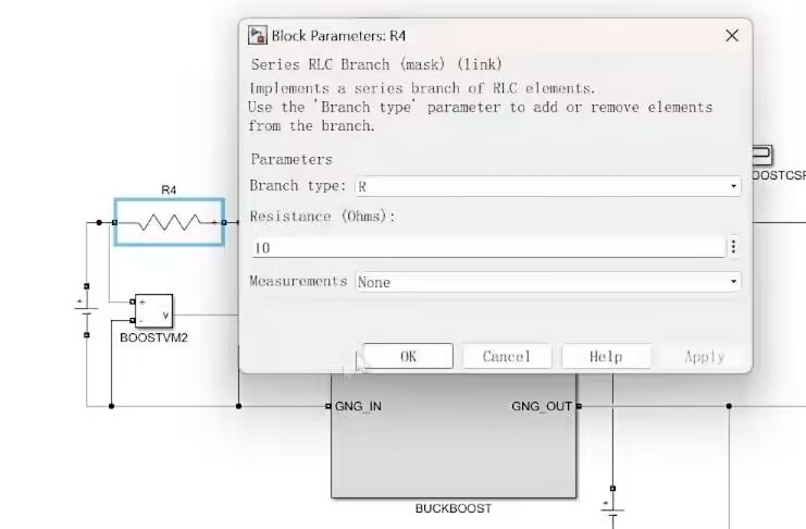
Diagram 1.3.4 Setting the Output Impedance of the Photovoltaic Panel Figure
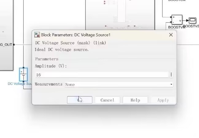
1.3.5 Setting the Battery Voltage
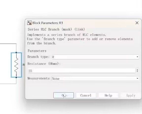
Figure 1.3.6 Setting the Output Resistance
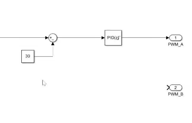
The fourth step is to edit the controller in the graphical interface. First, BUCK-BOOST, making the input voltage equal to the input current multiplied by the internal resistance to achieve MPPT, that is, the current multiplied by 10 and combined with the voltage to form a PID. Then enable PWMA in duty cycle mode. Then BOOST, set the voltage setpoint to 30, and enable PWMA in duty cycle mode.

Figure 1.3.7 Setting the Control Loop
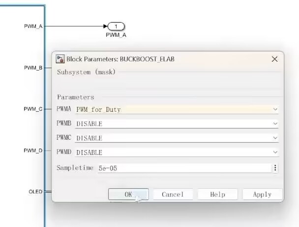
Diagram 1.3.8 PWM Diagram with Duty Cycle Mode Enabled
1.3.9 Editing the BUCK Controller
The fifth step is to click to compile.
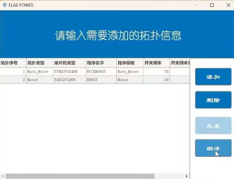
Figure 1.3.10
Successful Compilation After compilation, simulation testing can be performed. First, set the input voltage of the voltage source to 25V. You can see that the input voltage of the front stage is about 12.5V, and the output is 30V. Then set the input voltage of the voltage source to 55V. You can see that the input voltage of the front stage is about 27.5V, and the output is 30V. All parameters meet the requirements of the question, and the simulation verification is successful.
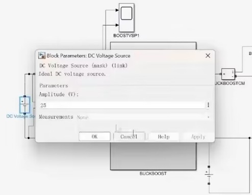
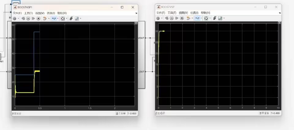
Figure 1.3.11 Simulation verification
step six: open the generated program, compile it separately, and after confirming that there are no compilation errors, burn the program to the two minimum system boards respectively.
Step seven: insert the minimum system boards into the corresponding power boards respectively, fix the power boards on the experimental platform and connect the wires.


Figure 1.3.12 Wiring
step eight: power on, and test the physical output under the premise of ensuring safety.
(1) When the input is 50V, the current of the input port is 2.49A, the internal resistance voltage division is half of the power supply box voltage, and the output is 30V.

Figure 1.3.13 Output when 50V input
(2) When the input is 25V, the current of the input port is 1.24A, the internal resistance voltage division is half of the power supply box voltage, and the output is 30V.
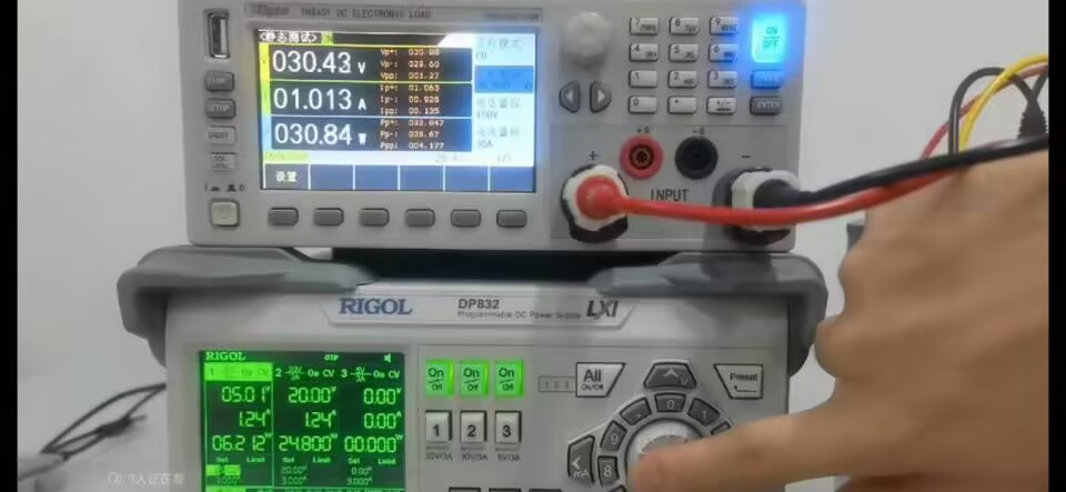
Figure 1.3.14 Output when 25V input
(3) With an input of 40V, the current at the input port is 1.99A, and the voltage division of the internal resistance is half of the power supply box voltage. At this time, the output is 30V.
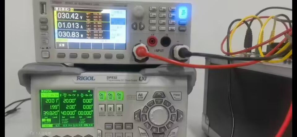
Figure 1.3.15 shows that all parameters of the output with a 40V input
meet the requirements of the problem, and the scheme is successfully verified.


 京公网安备 11010802033920号

 TK11140SIL


