Method of connecting discharge resistors in series with low voltage capacitor banks
Source: InternetPublisher:elleny Keywords: Resistors low voltage capacitors capacitor banks Updated: 2025/03/04
The discharge resistor of the low-voltage capacitor bank generally uses a 220-volt incandescent bulb, which also serves as an operating indicator light.
In order to extend the service life of the bulb and reduce power consumption, two bulbs of the same power can be connected in series and connected in a star shape. At this time, the voltage on each bulb is about 50% of the rated voltage and the power consumed is about 35% of the rated power.
Here is how to wire it:
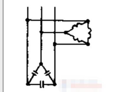
In order to ensure reliable automatic discharge during power outage, the discharge resistor should be directly connected to the capacitor bank, and a circuit breaker or fuse should not be installed separately for the discharge resistor.
In some cases, in order to reduce the power loss in the operation of the discharge resistor, an automatic device can also be used. When the capacitor bank grid is disconnected, the automatic device automatically puts the discharge resistor into the circuit.
- How do I choose the gain of an operational amplifier?
- Inverting Operational Amplifier Circuit Analysis
- Understanding the capacitance formula, what are the types of capacitors
- Summary of I2C basics: How does I2C communication actually work?
- Which one is better, NPN or PNP transistor?
- What is a Half Wave Rectifier? Working Principle of a Half Wave Rectifier
- Symbol/working principle/type/characteristics/application scenarios of depletion-mode MOSFET
- What does a rectifier do? What is the process of rectification?
- How to identify common mode interference? Methods to eliminate common mode interference
- Ideal characteristics of operational amplifiers/pin configurations/gain types/primary applications
- 555 square wave oscillation circuit
- 555 photo exposure timer circuit diagram
- Introducing the CD4013 washing machine timer circuit diagram
- Simple level conversion circuit diagram
- 555 electronic guide speaker circuit diagram for blind people
- Circuit diagram of disconnection alarm composed of 555
- Analog circuit corrector circuit diagram
- color discrimination circuit
- Color sensor amplification circuit
- Level indication circuit


 京公网安备 11010802033920号