LM4780 power amplifier
Source: InternetPublisher:OxXLshjcj Keywords: LM4780 power amplifier Updated: 2025/12/12
LM4780 power amplifier
Having decided to build an ultra-compact design, using a spare LM4780 seemed like an obvious plan. That said, I would probably have opted for a different integrated circuit if it weren't available. The LM4780 contains two LM3886 chips (reference) and provides 60 watts per channel, far exceeding what this application requires. National Semiconductor manufactures integrated circuits in various power levels and configurations, and there are many possible candidates suitable for this application—after all, we only need a few watts, as this amplifier primarily drives small desktop speakers.
Basic design requirements:
I envision the amplifier's design primarily referencing the Audax mini monitor cabinet it will drive. Therefore, the cabinet will have the same width and depth, although I don't actually plan to place the amplifier on top of the cabinet.
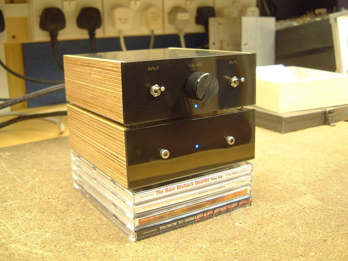
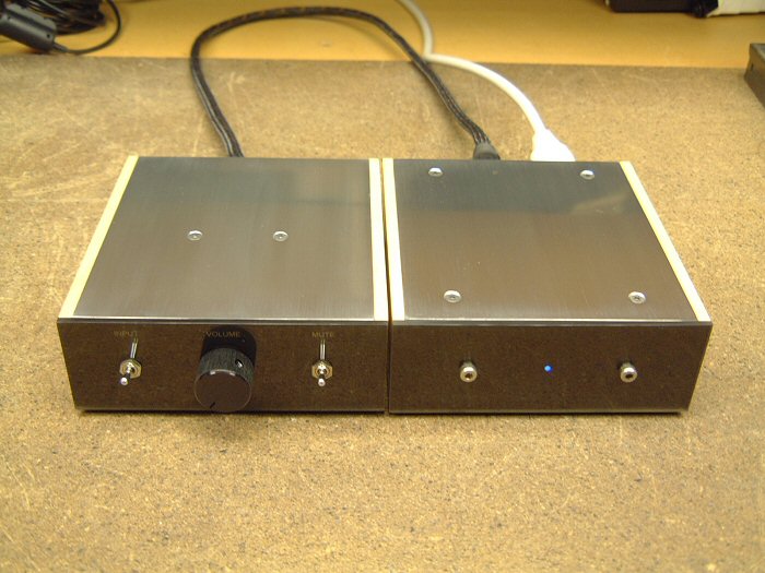
I also drew some design inspiration from my Musical Fidelity A1. The top panel acts as a heat sink—not the most efficient arrangement, but sufficient for this application. Additionally, since the actual amplifier can be much smaller than these speakers, I decided to recess the rear panel. This means all the connectors are hidden by the side and rear panels—a detail I've always loved about the A1.
Since this is primarily used as a PC amplifier, one input is sufficient. However, I added a second input to make the amplifier more "versatile," in case I decide to use it elsewhere.
While the amplifier could be shut down via the workshop's daytime circuit breaker, I think standby or silent mode would be useful, since the "external" power supply was originally intended to be hidden. The LM4780 has a "silent" function, which is easier and more preferable than any alternative.
Finally, due to its compact size, heat can be an issue. This means some form of thermal protection is needed. However, note that this isn't to protect the integrated circuits—these chips have comprehensive built-in protection and are perfectly capable of self-protection. Instead, it's to protect anyone who might come into contact with the amplifier. As mentioned earlier, the top plate acts as a heat sink, so its temperature should be kept within safe limits!
Inverted or non-inverted?
When I first built Gainclone in 2003, the inverted configuration was all the rage, with almost every forum member writing that it was far superior to the more traditional non-inverted layout. Since then, things seem to have changed, and now everyone says non-inverted is the right way. Perhaps this reflects more on group dynamics than amplifiers?
My LM3875 gainclones were inverting mode in the recorded experiments, but since writing down the results, I briefly tried non-inverting mode and must report that the difference is indeed very small. In context, upgrading the power supply to dual-mono operation makes a significant difference. That said, YMMV (your mileage may vary), because the inverting mode presents a much lower impedance to the preamplifier—I wouldn't be surprised if some reported differences are due to this. This can be easily tested by connecting the input resistor in the inverting amplifier in parallel with the input of the non-inverting version.
Therefore, I chose a non-inverting configuration for this amplifier because it allows for a more reasonable input impedance...
power supply:
Due to space constraints, the PSU will be a single unit, supplying power to both channels. Furthermore, using separate power supplies for the left and right channels is inconvenient—point-to-point wiring is difficult enough!
The star ground point will be implemented directly next to the integrated circuit. The external PSU will generate a pair of completely independent power potentials, becoming a "split" power supply only when connected through this star ground.
After completing the amplifier prototype design and construction, I conducted some preliminary experiments to determine the optimal power supply configuration. I say "preliminary" because my reference high-fidelity equipment is currently stored away due to a move. However, using workshop high-fidelity components (Technics SLPG480 and Rogers dB101) and my LS3/5a, I determined the following:
Each rail has a 220uF decoupling capacitor directly mounted on the chip (Panasonic FC).
The PSU has 6600uF smoothing capacitors per rail, consisting of 3300uF, 35V Panasonic FC capacitors. I tried a range of values and several different types, but these gave the best results. Parallelizing a pair of 3300uF capacitors can halve the component's ESR and ESL, and these sound better than the single, cheap, unnamed 10,000uF device I tried.
I used snubbers at the power supply, but couldn't hear a significant difference using the test source and speakers. I'm wondering if tightly twisted pairs in the special power supply umbilical wires are a problem? I did find that adding 100nF per rail at the power supply helps reduce the effects of mains-bourne interference (although this amplifier seems very good in this regard—much better than the current Arcam Alpha 2 in the workshop). A future item (when ATC is available again)—try adding snubbers to the integrated circuit...
Using this amplifier and the available source components and enclosures, I could not hear any notable difference between the standard bridge and the discrete MUR860.
The 120VA 18V transformer I used for the original gainclone prototype sounded fine with this low-power amplifier. I tried a 200VA driver and couldn't hear a significant difference using available speakers.
Aside from initially powering the amplifier from the bench power supply, I didn't attempt any further voltage regulation. I feel that the sound quality achieved by these measures easily exceeded my expectations and requirements!
The power supply has an LED powered by an extra winding I added to the transformer—about 30 turns of fine enameled wire. However, I didn't want the LED to blink at 50Hz, so I added a simple half-wave rectifier.
Simulation Design:
This schematic diagram shows the analog signal path:
The input signal is applied to the source selection switch, a DPDT toggle switch with gold-plated contacts. From there, the signal passes through an ultrasonic filter (R1 and C1) and is applied to the volume potentiometer, whose corner frequency is approximately 2-300 kHz at typical source impedance.
From the potentiometer, the signal is passed to the power amplifier integrated circuit via C3 and R5. R5 ensures the amplifier remains stable during power-on and power-off cycles and eliminates the risk of parasitic oscillations when the volume control is near or at its minimum value. During normal use, it does not act in the signal path because the input does not draw current at audio frequencies, therefore there is no voltage drop across it.
The feedback resistors were chosen to give a convenient gain value (x25.54, or 28dB). This was simply a low value chosen to avoid Johnson noise (combined impedance less than approximately 2K), while also ensuring they were components I had in stock.
Finally, there's an output Zobel network. Gainclones are often synonymous with simplicity, a design philosophy that typically leads to omitting these components. My initial prototype didn't have them, but I found that adding them improved the amplifier's RF immunity. As always, YMMV.
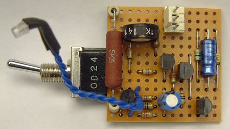
Control circuit:
None of my projects have fewer than a few transistors!
The complete circuit is simpler than it appears. There are three distinct parts—a temperature sensing circuit, an LED blinker, and a power supply—and as you will see, these blocks are tightly integrated, resulting in a low component count.
To avoid unbalanced power supply and unnecessary DC current in the ground scheme, the entire circuit is positioned between the positive and negative power rails. Since the silent connection of the integrated circuit requires a pull-down to the negative power rail, the temperature sensor is placed on this rail.
The sensor is a classic 2-transistor Schmitt trigger. TR2 directly switches the silent current—it's one of only two components in the entire design that "sees" the entire 50-60 volt supply voltage, hence it's a BC546.
For reasons explained later, the sensing circuit operates at 3.3 volts. RT1, an NTC thermistor, is connected in a potential divider that feeds the input to the Schmitt trigger. As the temperature rises, the potential at the base of TR1 rises. At some point, it can begin to conduct, and when this happens, TR2 begins to turn off. As the collector current of this device decreases, the potential on R17 also decreases. However, the emitter of TR1 is connected to this point, so this means that the VBE of TR1 increases, causing it to conduct more. This is positive feedback and will cause the output current to sharpen and clean down. The 33-ohm resistor introduces hysteresis, meaning that the temperature must drop below the original "jump point" for something to return to normal operation.
The mute switch is connected across a thermistor; when activated, it simply short-circuits the device, simulating a severe overtemperature condition. Therefore, the audio is muted.
This circuit requires a small operating current—in microamps, rising to approximately 3mA when the mute switch is activated. The power supply for this sensing circuit is simply regulated to 3.3 volts by a Zener diode ZD1, with decoupling provided by C10. Current is supplied through R22, but note that the power LED is placed in series. This is an economical way to power both the sensing circuit and the LED. By powering this circuit between the two rails, the resulting high-value dropper resistor provides approximately constant current drive, ensuring relatively constant LED brightness and preventing significant drops in power rail under load.
The final part is the LED blinker. Two transistors form a classic two-end blinking circuit, which is usually placed in series with the load. However, I've placed this circuit in parallel with the load. This means that when the transistors are on, the LED is short-circuited. When the LED lights up, there's a sufficient voltage drop across it to power the blinking circuit (approximately 3.5 volts). Surprisingly, it works just as well when using green or yellow LEDs (VF≈2V), and it also works with red LEDs (VF≈1.5V) when the resistance value is changed.
Deciding to parallel the circuit is a good move. Since all components in the blinking circuit operate from the forward voltage drop of the LED, they do not need to be rated to withstand the 50-60 volts available on the power rail. Therefore, standard BC548/558 devices can be used, and the timing electrolytic capacitor can be a small, low-voltage device. However, all of this depends on the presence of the LED in the circuit, so for this reason, the LED must be soldered in place (i.e., not on a separate connector). If the LED fails, it may short-circuit, which is perfectly safe, but if it is open-circuited, there is a slight possibility of a problem. However, the 5K6 resistor will limit the available current to approximately 10mA, which should prevent any nasty explosions.
Finally, note that D1 connects the flashing circuit to the sensor output. When the temperature is normal and the mute switch is in the "unmute" position, the voltage on the collector of the BC556 will be close to 0V (relative to the negative rail). Therefore, the diode conducts, preventing TR4 in the flashing circuit from conducting. As a result, the LED remains lit. When muted, the voltage on the BC546 rises, the diode becomes reverse biased, and the LED begins to flash.
This explains why the temperature sensor's power supply is so low (3.3V). When silent, the voltage at the base of the TR4 transistor is negative relative to its emitter, which remains at 3.3V. There is a limit to the amount of reverse bias that a transistor can apply to the base-emitter junction—typically around 5 or 6 volts. A Zener diode ensures that the reverse bias remains below approximately 3 volts.
Therefore, a simple, small circuit with a low component count should be reliable because only one component generates heat, and this has been over-specified by 4 times.
Build:
I used point-to-point wiring with this amplifier—it was challenging because the LM4780's pin spacing is so tight, but it was faster and easier than designing the PCB and etching it...
My point-to-point routing approach differs from most examples I've seen, where connections rely on solder for mechanical strength. This is detrimental to long-term reliability, especially in power amplifiers operating at high temperatures. Furthermore, the tight 3D layout resulting from this construction technique makes future maintenance difficult due to compounding issues.
I firmly believe that all connections should rely on physical bonding, not solder. Therefore, all connections are made by securely twisting wires together. This is more time-consuming and very fiddly, especially at the beginning. However, as it progresses, it becomes easier than a "normal" p2p construction, where the heat from soldering new connections can damage previously made solder joints—in extreme cases, components literally detach! It's incredibly frustrating when this happens!
As mentioned earlier, I wanted to complement the design of my Audax mini monitor amp by using birch plywood for the side panels, and also using the same dimensions. I quickly realized that the amplifier could be much smaller than the amp, so I decided to use the extra depth to conceal the connectors. The extra surface area of the aluminum top plate helps with heat dissipation. Ignoring this "dangling," the amplifier measures only 12.5 x 7 x 4.5 cm—is that the smallest chip-amp?
Assemble the amplifier:
The LM4780 has 27 pins, spaced only 1mm apart. Eight of these are not connected to anything and can be removed. Next, the pins are straightened and pointed to one of three basic orientations—horizontal for power, vertical for signal inputs and outputs, and 45 degrees for ground and mute connections.
For the wiring, I decided to use enameled wire. This has a built-in safety feature—the chance of a short circuit is greatly reduced if the internal wiring is disturbed.
The enameled coating burns off when given sufficient soldering iron heat. However, I'm unsure if the resulting fumes are health-friendly, and I'm also not satisfied with the amount of time required for this process. It's fine for assembling crossovers, but not for microsurgery on tiny chip amplifiers. Therefore, using a scalpel, I prepare the wires by scraping off the enameled coating and pre-tinning the exposed copper wires:
Prepared integrated circuits and wires (28K)
The next image shows the initial connection. The chip is held in a vise, and the prepared wires have been loosely attached to a pin with tiny solder pads. Note that all pins are color-coded with permanent markings—just to help prevent any silly mistakes!
If you look closely at the two "black" pins in the middle, you'll see that they are carefully wrapped around the wire, ready for soldering.
First connection (35K)
Here, two power leads have been successfully attached to the integrated circuit. They are separated by a few millimeters, but the enameled insulation will prevent any nasty surprises.
Two power supplies connected (29K)
Next, I move on to the signal connections and add the 27K feedback resistors you see below. These resistors are 1/8 watt – approximately 3mm long. The output and inverting input pins have been folded back, and the resistors sit on top of the package. Also note some green sleeves that have been applied to the ground pins:
Feedback resistor (32K)
The next additions are a ground wire (using the same technology as the power connection) and a 1K1 resistor connected between ground and the inverting input. These resistors are larger 1/4-inch versions because they were available in my parts box.
Ground and silent connection (27K)
With the ground wire in place, I can now consider the components needed for the non-inverting input. Before installing these, I connected the two "mute" leads with some finer enameled wire, cutting them short so they don't touch the next resistor. This image shows the 1/8 watt 1K and 22K resistors. I also added some green sleeves to the non-inverting input for peace of mind. Notice how the various resistor leads form the input and output connections...
All resistors are installed (28K).
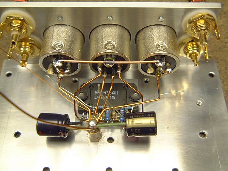
Finally, this view from below shows the power rails and ground more clearly. I'm very happy with the result, and now I'm able to quickly test the assembly to prove I haven't made any silly mistakes. Obviously, it's too early to judge any sound quality!
Building a chassis:
This is constructed entirely from recycled or leftover materials. The side panels are formed from remnants from hollowing out mini monitor cabinet layers, and the metal was rescued from skip! The smaller corner pieces are 25mm x 40mm, and the larger pieces are approximately 50mm x 100mm!
Raw materials (26K)
The first step is to make the side panels—here, two layers of 23mm birch wood are glued together. This requires extensive planing and sanding...
Side panel in progress (56K)
I decided to use a 9.5mm slotted drill bit to cut the chassis and top/bottom plate recesses in the router—this will be easier than making the jigs for the boot router. However, this relies on the panels being perfectly straight inside. This is a good thing because I like my project to be as perfect inside as outside ;-)
Completed side panel (52K)
This is the chassis, after most of the drilling is complete. As you can see, various sockets have been installed, and integrated circuits have been attached. Note that the sil-pad is large enough to cover point-to-point connections—just in case.
Chassis with integrated circuits (41K)
Final wiring for the audio section:
At this point, things became very difficult to reverse. Therefore, I had to make sure the chassis mechanics were complete before proceeding to the final stage of wiring.
This image shows the star ground connection and the connection to the XLR socket. Additionally, we added 220uF decoupling capacitors (Panasonic FC – long-life, high-temperature devices). The leads on these could have been shorter, but the capacitors interfere with the volume potentiometer – I can shorten the leads if I ever replace the potentiometer in the future.
I chose to use XLR sockets for several reasons. The most obvious is their robustness and very high quality. However, I was concerned about using standard 4mm binding posts when they were so close to the input connectors. This is a non-inverting amplifier, and any stray capacitance between the input and output connectors would create a positive feedback path, posing a very real risk of the amplifier turning into an oscillator! The grounding of the XLR sockets provides good shielding, reducing this risk. This is something that people building compact amplifiers sometimes overlook!
Chassis wiring (52K)
The next step is to install the input cabling. The cable is a high-quality video lead, rescued from an old VCR. I utilized the existing termination for neatness. Note the P-clamp that helps keep the cabling tidy. The black wire is the "pigtail" connecting to the screen for signal ground.
Additionally, output wiring has been added, including Zobel components mounted on the output sockets. Ideally, these would connect directly to the integrated circuits and star ground, which I might be concerned about if this amplifier weren't so compact.
Input wiring (52K)
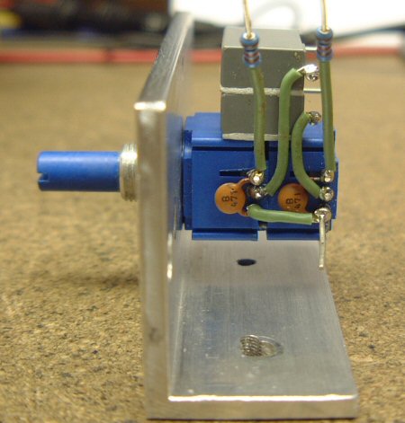
Moving forward, the potentiometer assembly is complete. The input capacitor and ultrasonic filter can be seen here. The gray 2u2 capacitors are secured with double-sided adhesive pads, and as you'll see later, their placement is for a reason... Also note the signal ground, the lower right pin...
Potentiometer and front sub-panel (47K)
The subpanel is then secured to the chassis... Signals from the input switches are passed to the potentiometer via a 1K resistor. Notice the soldered connections to the right of the capacitor—these were made using a substandard method I've tried to avoid elsewhere—which do contrast sharply with the secure connections to the left of the capacitor. However, there's a reason for this. I anticipate I might need to desolder the potentiometer from the chip assembly at some point in the future, so I made these connections easy to desolder. I'm not too concerned about reliability here, as it's the easiest to access if necessary.
Front panel mounting (48K)
The final detail is adding the connection between the chassis and the star ground, as shown here:
Star grounding (30K)
Install thermal sensor/silent/LED board:
Since the thermal sensor doesn't need to be in close contact with the integrated circuit, I decided to minimize internal wiring by placing it directly on the control board. The power LED is also directly connected to this board—it's a standard 3mm device, filed down for better fit into the 3mm front sub-panel.
The 2W power resistor is rather over-specified—its actual power consumption is approximately 0.5 watts. However, I have a spare, and using a larger resistor will help with reliability by keeping the operating temperature low.
Control circuit (28K)
This small assembly is entirely supported by a toggle switch, as shown here. A recess is drilled in the chassis for the placement of a thermistor, and a plastic insulating sleeve is fitted to the M3 support. There are two supports to which the base plate is attached.
Also note how the gray input capacitor secures the LED in place:
Control circuit installation (41K)
Front panel:
This project gave me the opportunity to try out an idea I had years ago—to create a professional front panel using overhead transparency film.
This image shows transparency. If you look closely, you might notice a black square around the LED—this is because the opening is 2mm—smaller than the actual LED. One layer lacked contrast, so a second layer was applied using a piece of white tape from my labeler, which also acted as a defuser to ensure good, even lighting.
Front panel (21K)
Here it is, mounted on the chassis along with the acrylic glass, which is simply held on by the switch and potentiometer holder. You can see through the transparency because the toner coverage isn't very thick, but this isn't a problem when the chassis is fully assembled, as there's no light source at the back.
Front panel assembly (32K)
The text visibility is barely acceptable—the acrylic is tinted, but not very heavy. The aluminum is polished to make it as reflective as possible, but I applied some white tape to improve contrast. Another option would be backlit inscription, but that's not feasible here without significant modifications to the chassis and front sub-panel.
power supply:
Initially, I assumed that an external power supply would be a simple matter—for example, built into a standard die-cast aluminum housing. Since it was intended to be hidden, there were no physical limitations on the electrical design.
But once the design was finalized, I began to realize how compact it could be. It quickly became apparent that I could fit everything into a single box that matched the amplifier...
Therefore, the final solution uses birch plywood side panels, two corner pieces to form the chassis, and 1mm aluminum to form the top and bottom panels—these panels clamp the toroidal transformer in place.
The first step is to prepare the chassis. Two corner pieces are cut off, and a circular opening is cut to allow for the transformer. Installing the 120VA transformer into a 45mm high box will be very tight—this time there's no question of recessing the rear panel to hide the connectors!
Next, we'll make the wooden side panels. These are a bit easier because the 9.5mm groove doesn't have to stop at one part of the piece. You can see the groove continues along the back panel... Also, an area must be removed to make way for the smooth capacitor.
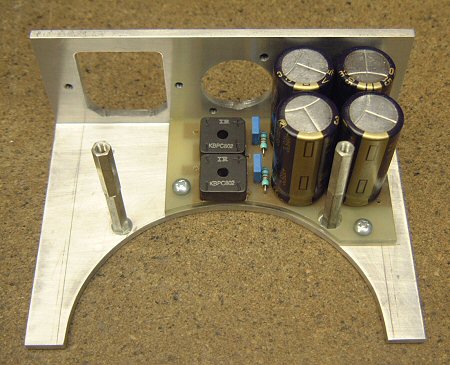
Next, I made a PCB for the power supply. Like the gainclone prototype, this was made using a scalpel, and excess copper was removed using the heat of a soldering iron. You can't see it here, but I also made an insulator to sit between the PCB and the chassis. I used a very thin sheet of FR4, necessary because space was limited.
This view shows the PCB's underside—as you can see, the layout is very simple. To save height, component leads are laid flat before soldering—this also ensures better contact but makes future maintenance a bit more difficult. To act as spacers, I used some plastic bushings—the kind typically used to insulate semiconductors from heat sinks.
This is the complete PCB in place. Notice how the DC output XLR connector just clears the bridge rectifier—a clean and simple solution. You can also see the spacers attached to the baseplate...
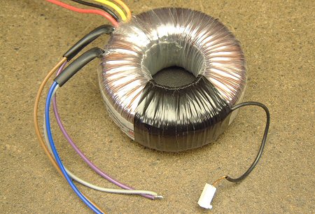
Next, I added a winding to the transformer to power the LED. This winding provides about 5 volts, which, from memory, requires about 30 turns. Due to limited space, I used very thin enameled wire, without significantly changing the height. The winding was secured with insulating tape—the end of the tape runs at the top of the transformer, so transformer clamping will keep the tape secure...
This is an LED rectifier. I didn't want the LED to flicker, so I added capacitors.
This is how it's mounted on the other half of the chassis. Like the amplifier, the 3mm LED is filed down and positioned in the hole. The LED holds itself in place but is additionally retained by the transformer.
Next comes the final assembly. Wires from the XLR connector and transformer secondary winding are attached to the PCB, and the primary winding is wired up. Note the green ground wire securely connecting both halves of the chassis to the green ground wire of the mains ground connector in the IEC socket—as well as the XLR socket housing ground.
I also added an insulator to the top of the capacitors. As they age, they could swell and contact the base plate, causing a short circuit. You can see the acrylic front panel, which, like the amplifier, has a laser-printed transparency marking to define the power LEDs (there's no text yet, but that may change). Since there are no controls (or even space for a power switch), the front panel is held on with a pair of nice stainless steel hex bolts.
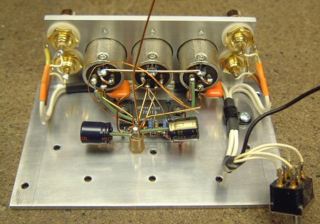
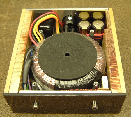
This is the final assembly, with two wooden side panels attached. These hold the two halves of the chassis together—the thin top panel helps, but it primarily holds the transformer in place... As you can see, it's a squeeze—the PCB fits perfectly. You can see the four spacers attached to the base plate—these are covered with neoprene "Hellerman" sleeves to protect the transformer from movement and contact with them.
Finally, here's a top view before adding the top panel. This panel is secured by four hex bolts, concealing all other fasteners, including low-tech wood screws. This suggests we really couldn't afford a 3mm thick chassis...
The final construction worked well—because the internals were dominated by that 120VA toroidal transformer, and the resulting unit was quite heavy for its size.
in conclusion:
Due to the relocation, this project was built without a workshop and all the resources for high-fidelity audio, but despite this, I am satisfied with the design and construction. Once I remove the reference ATC from storage, I will only be able to conduct a full evaluation of the absolute sound quality and potentially improve things...
As a finished product, this amplifier is quite adorable and has garnered a lot of positive feedback from friends and colleagues. Design details, including the concealed connectors and the use of birch plywood, contribute to its charming appearance.
The LM4780 runs slightly warmer than the LM3875 because it has a higher bias in the output stage. Some people report that the LM4780 runs very hot, but the problem isn't as severe as you might think. If you have a hot-running parallel design, study the datasheets and ask yourself if you can really omit everything—minimalism is good, but within constraints!
The quiescent current is approximately 50mA per channel—compared to about 17mA for the LM3875. At a 30V power rail, this translates to 6 watts of heat when there is no signal—the chassis operates at about 12-15 degrees Celsius above ambient temperature when there is no signal. I quite like this heat—it reminds me of my old Musical Fidelity A1… Fortunately, because music has a high PMR (peak to average ratio), moderate use won't raise the temperature too much—the large amount of aluminum present in the chassis helps with this, as it results in decent thermal inertia. The overhanging top plate also helps, although it's only 1mm thick—surface area is important for heat dissipation, and although it's not optimally aligned for good convection, you can feel a healthy stream of hot air rising from below the rear of the panel. Thermal sensors will silence the amplifier before the chip reaches unsafe limits, ensuring reliable long-term operation.
- 18-watt audio amplifier
- Class A headphone amplifier
- Audio digital-to-analog converter
- Hybrid headphone amplifier
- LM3886 monaural amplifier
- High-fidelity headphone amplifier
- 10W audio amplifier with bass boost
- 5 Watt Class A Audio Amplifier
- Connection between power supply and voice integrated circuit
- Single chip speech recognition circuit
- car stereo power amplifier
- TDA7056A power amplifier circuit diagram
- TDA1904 power amplifier circuit diagram
- TDA1552Q power amplifier circuit diagram
- TDA1521 power amplifier circuit diagram
- TDA1015 power amplifier circuit diagram
- TA7769P power amplifier circuit diagram
- TA7205AP power amplifier circuit diagram
- TMOS application circuit
- 120W power amplifier with detailed treble


 京公网安备 11010802033920号