Phase detection circuit composed of TLC072 and MAX4521
Source: InternetPublisher:通通 Keywords: Detection circuit Updated: 2024/09/05
The figure below shows a phase detection circuit composed of a dual op amp TLC072 and an analog switch MAX4521. It can be used as a phase detection circuit in a phase-locked loop (PLL) circuit and a lock-in amplifier. The circuit has two output terminals. When a sine wave signal is input to the analog input terminal and a square wave signal with the same frequency and a duty cycle of 50% is sent to the logic input terminal, the detection waveform shown in the right figure can be obtained at point A in the circuit according to the phase difference between the two signals. The op amp IC1b and the surrounding resistors and capacitors form an active low-pass filter to average the detection signal at point A. The gain of the active low-pass filter is determined by the ratio of resistors R5 and R4, and its frequency characteristics are set by resistor R5 and capacitor Cl.

Capacitor Cl should be a film capacitor with small tarσ. In addition, ICla uses a full-swing operational amplifier to expand the input and output voltage range. IClb is best to use a CMOS operational amplifier.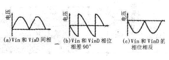
The figure below is a phase detection circuit with high gain accuracy (error is 0.1%). IC1a forms a follower to act as a buffer. IC1b forms an inverting amplifier with a gain of -1 to act as an inverting amplifier. IC3 (74HC4053) is a two-choice switch that selects the output signal of IC1a or IC1b. IC2a is also a follower that acts as a buffer, and IC2b is an active low-pass filter like IC1b in Figure 1. The switching control of IC3 is achieved by controlling the input level of the Sn pin (11). The waveform at point A in Figure 3 can also refer to the waveform on the right.
The power supply voltage of the above two circuits is ±5V, the current consumption does not exceed 10mA, the input and output voltages are both below 4V, and the applicable frequency range is 10kHz~100kHz.
- Does lithium iron phosphate battery need a protection board? The correct way to charge lithium iron phosphate battery
- What is the difference between MOSFET and BJT? Which one is better between MOSFET and BJT?
- What does a rectifier do? What is the process of rectification?
- Ideal characteristics of operational amplifiers/pin configurations/gain types/primary applications
- Analysis of the basic principle of measuring resistance by bridge method
- TL494 pin functions/configuration/ratings/operating conditions/layout diagram
- Important things to know about PCB routing and how to design the right routing for your PCB
- What is the difference between high-side and low-side resistive current sensing
- Using an Op Amp to Drive a Simple and Practical Power Amplifier
- Circuit diagram of a differential amplifier circuit
- IF amplification and detection circuit in AM radio
- Full-wave synchronous detection circuit using analog switch IC
- Half-wave synchronous detection circuit composed of switching circuit
- Large signal diode detection circuit
- Detection circuit diagram
- Integrated detection circuit diagram
- Integrated detection circuit
- Ringing detection circuit
- Integral (quadrature) detection circuit for light-emitting diodes
- Vibration frequency measurement optical fiber sensing signal same frequency detection circuit


 京公网安备 11010802033920号