The Universal Serial Bus (USB) is quickly becoming the standard interface for most PC peripherals. It is replacing RS-232 and parallel printer ports because of its speed, flexibility, and support for hot-plugging of devices. Industrial and medical device manufacturers are also eager to use this bus, but adoption has been slow because there is no good way to provide the necessary isolation for machine connections that control dangerous voltages or for low-leak, defibrillation-proof connections in medical applications. .
The ADuM4160 provides an economical and simple way to implement isolation buffers for industrial and medical peripherals. Challenges that need to be addressed include:
The circuit shown in Figure 1 isolates a USB-enabled peripheral. Since this circuit does not have clearly defined peripherals, the power supply for the secondary side of the isolator is provided as part of the solution. If the circuit is built on the peripheral's PCB, power can be obtained from the peripheral's offline power supply, the battery, or the USB cable bus power, depending on the application needs.
The application circuit shown here is typical of many medical and industrial applications.


The power used by the upstream USB connector is derived from the 5 V VBUS voltage provided by the USB cable. The peripherals must provide all signals and pull-up/pull-down resistors required when the ADuM4160 is not used. Power on the downstream side is provided by a wall power adapter and the ADP3338 LDO regulator (5 V option). This LDO provides very low dropout voltage, reducing wall power adapter regulation requirements. Its small size (SOT-223) and 1 A current capability are ideal for general-purpose circuits where peripherals may require cable power to operate.
The ADuM4160 has multiple power, speed, and protection options that must be determined. The first is the operating speed of the peripheral. Peripherals operate at one of three speeds: low speed (1.5 Mbps), full speed (12 Mbps), and high speed (480 Mbps). The ADuM4160 does not support high-speed operation and blocks the handshake used to negotiate that speed. Overspeed mode starts with a full-speed configuration, and the peripheral requests high-speed support through a process called high-speed chirping. The ADuM4160 ignores this high-speed chirp, so the high-speed operation request is never passed to the host and the peripheral continues to run at full speed.
The peripheral speed on the USB bus is either low speed or full speed. The required speed is determined by the specific peripheral, and the ADuM4160 must be set to match this speed through the state of the SPU and SPD pins. In the current schematic, the SPU and SPD pins are connected to the 3.3 V internally regulated supplies VDD1 and VDD2, thereby setting the device to run at full speed.
The 5 V power supply can be provided through the VBUSx pin, and the 3.3 V signal voltage is generated at the VDDx pin by the internal 3.3 V regulator. Alternatively, this 3.3 V supply can be provided to VBUSx and VDDx and the device can use the external supply directly, thus disabling the internal regulator. This option is provided to allow the ADuM4160 to be powered either from a 5 V USB cable or from a 5 V or 3.3 V power rail provided by a peripheral. The circuit shown accepts 5 V from each side, with the internal regulator active.
The ADuM4160 also offers an option to delay the application of an upstream pull-up resistor under peripheral control. This feature is controlled by PIN entry. In this application, the PIN input is jumpered high, so the upstream pull-up resistor is used whenever peripheral power is applied. In other applications, it can be connected to a controller's GPIO pin, a fixed delay circuit can be used, or it can be connected like this circuit. How to use this feature is up to the designer.
This circuit also includes protection components. These devices are selected from manufacturers that offer a variety of different devices, and the specific device chosen allows them to be replaced with a 0 Ω short-circuit resistor to remove it from the circuit. Designers should carefully consider protection device selection, ranging from situations where external protection is not required to a full suite of transient suppressor and filter components. The components included in this circuit show a typical highly protective configuration.
When the circuit is working, packet detection occurs and data is transferred from one side of the isolation to the other. The data shown below illustrate typical full-speed processing in both time domain data and eye diagram form. In real-time data, characteristics to note are that the packet starts in the passive idle state, which transitions to the driven J state, and that the end of the packet at the end of processing shows a single-ended 0 state, followed by the idle J state. It is this automatic control flow and handling of these special logic states that makes the ADuM4160 chip unique on the market.
The data shown in Figures 2 and 3 below are generated during the USB-IF certification process. Figure 1 shows a test packet being transmitted from the ADuM4160 upstream port to the host. Note the pre-idle state, where the passive resistor network remains in the idle J state. The center part of the pack is a mix of Jack and King. On the right side of the packet is the EOP (End of Packet) flag, which is a single-ended 0, followed by a driven J state, and then transitions to an idle J state.


The following are applicable test references:
Figure 3 is a full-speed eye diagram, showing that the ADuM4160 is able to provide a fully open eye, well away from the no-go zone. Similar data were obtained for the low-speed evaluation.


A photo of a typical application circuit is shown in Figure 4. The ADuM4160 evaluation board (left side of photo) is connected to the evaluation board for the AD7991, a 4-channel, 12/10/8-bit ADC with an IC-compatible interface . The ADC evaluation board acts as a peripheral, connecting to a PC via a USB port (in order to test and evaluate the ADC). This provides total isolation between the ADuM4160 USB port and the ADC evaluation board.
The edge speeds of this circuit are very fast, and in order for the system to pass EMI/RFI testing, excellent layout, decoupling, and grounding techniques must be used. For guidance, please refer to Tutorial MT-031 , Tutorial MT-101 , and Application Note AN-0971. For the complete layout and Gerber files for the ADuM4160 USB Evaluation Board Isolation Adapter shown in Figure 4, please visit: http://www.analog. com/CN0160-DesignSupport .


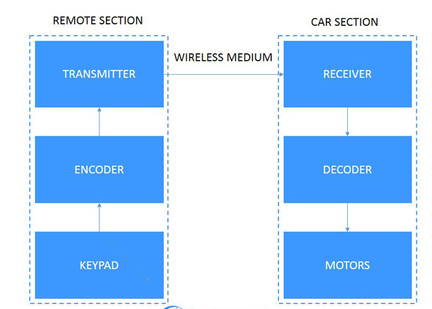
Blockdiagram
All reference designs on this site are sourced from major semiconductor manufacturers or collected online for learning and research. The copyright belongs to the semiconductor manufacturer or the original author. If you believe that the reference design of this site infringes upon your relevant rights and interests, please send us a rights notice. As a neutral platform service provider, we will take measures to delete the relevant content in accordance with relevant laws after receiving the relevant notice from the rights holder. Please send relevant notifications to email: bbs_service@eeworld.com.cn.
It is your responsibility to test the circuit yourself and determine its suitability for you. EEWorld will not be liable for direct, indirect, special, incidental, consequential or punitive damages arising from any cause or anything connected to any reference design used.
Supported by EEWorld Datasheet
EEWorld
subscription
account

EEWorld
service
account

Automotive
development
community

Robot
development
community

About Us Customer Service Contact Information Datasheet Sitemap LatestNews


Room 1530, 15th Floor, Building B,
No.18 Zhongguancun Street,
Haidian District,
Beijing, Postal Code: 100190
China
Telephone: 008610 8235 0740
 京公网安备 11010802033920号

 070922FR015S401CY