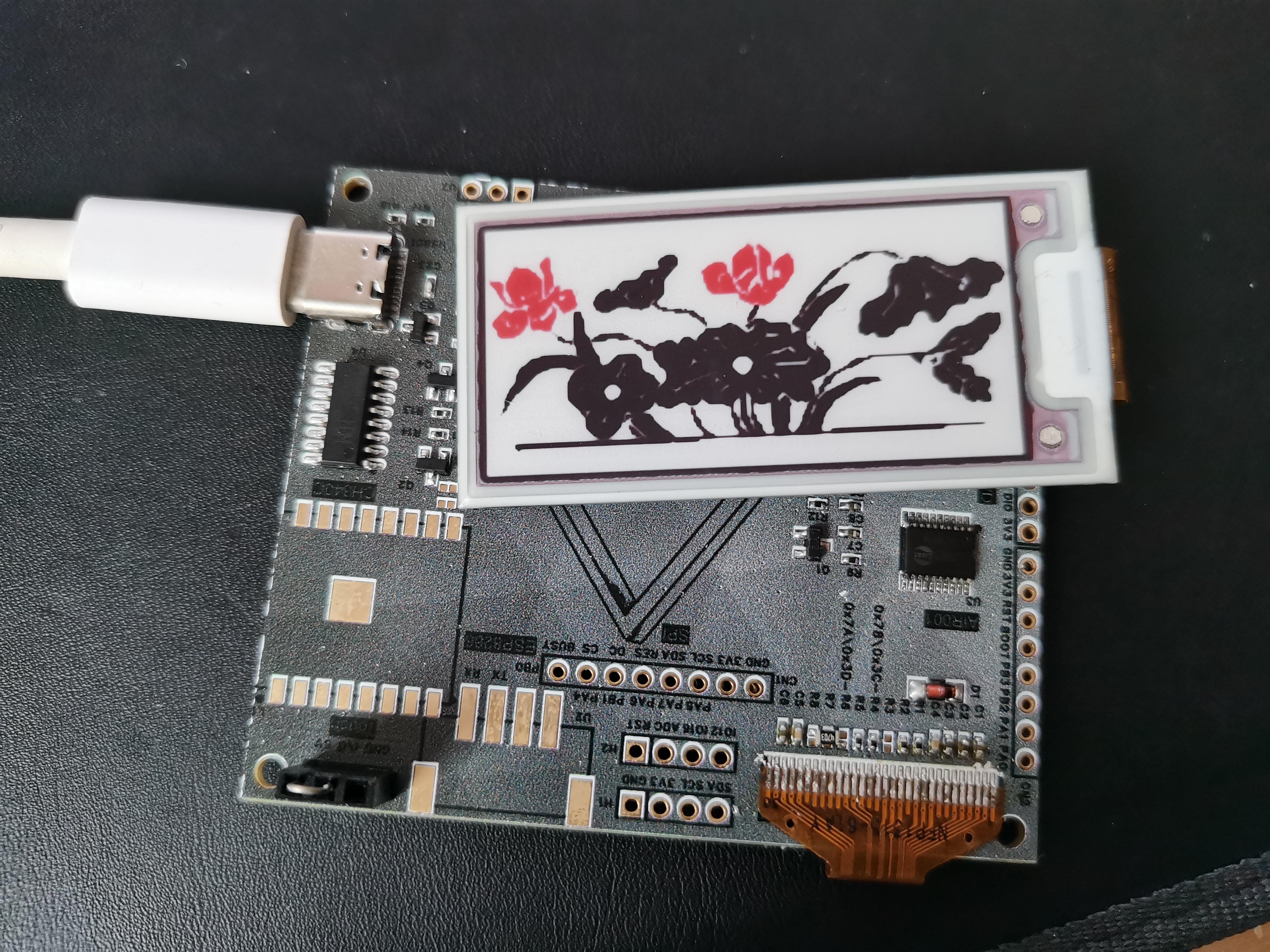
Main function: Integrates with Taobao's seven-in-one air quality monitoring module for MQTT forwarding and data display.
Secondary functions: E-ink driver board, OLED driver board, AIR001 minimum system.
LCSC manufactures at least 5 boards at a time; it would be a waste not to make more (although the intended use hasn't been decided yet).
. Revision history: 1. Replaced the E-ink ribbon cable connector with a universal flip-top connector. 2. Modified the OLED IREF resistor to a single 470K resistor. 3. Changed the capacitance of capacitor C22 in the E-ink driver from 100pF to 100nF.
Note: Some component selections are limited by personal component inventory; please modify accordingly.
Altium_based on ESP12S_Hezhou AIR001 universal e-ink screen_OLED driver board.zip
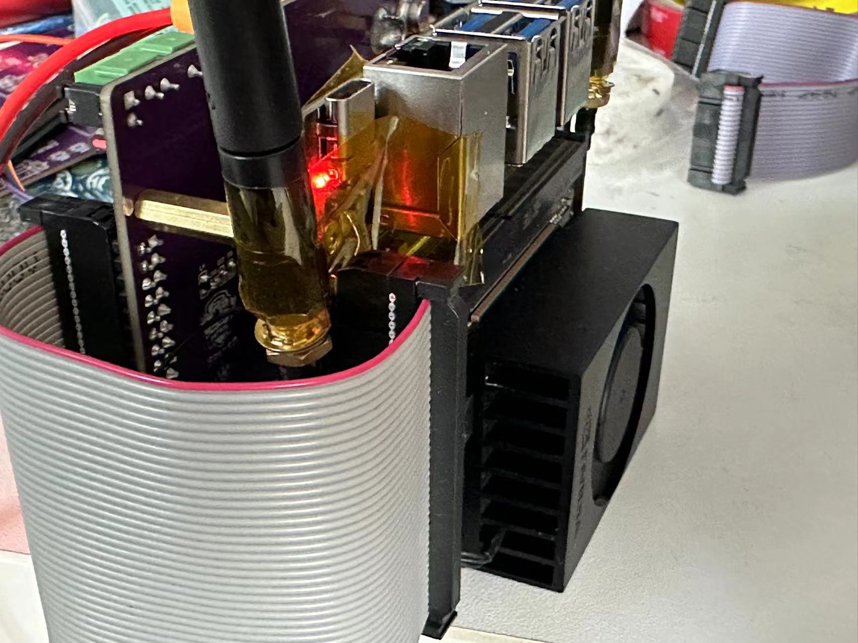
This project is the lower-level control board for a robot dog, connected to the upper-level computer via a 40-pin ribbon cable. The main controller consists of two STM32H750RCT6 chips, with 4 CAN channels and 2 SPI channels. The onboard power supply system has a 24V input and outputs of 19V, 5V, and 3.3V.
This project is the lower-level control board for a robotic dog. It connects to the upper-level computer via a 40-pin ribbon cable and can be fixed to the upper-level computer using M3 copper pillars. The main
controller consists of two STM32H750RCT6
microcontrollers with four CAN bus channels, each channel supporting three servo joint motors, for a total of 12 motors. The maximum baud rate is 1 MHz.
Two SPI channels handle communication between each microcontroller and the upper-level computer, with a maximum baud rate of 15 MHz . The board includes
an MPU6050 gyroscope and
three DC-DC synchronous step-down converters: 24V-19V, 19V-5V, and 5V-3.3V. The 19V power supply provides the upper-level ORIN NX (XT30) power to the robotic dog, while the 5V and 3.3V power the microcontroller systems.
A power distribution board is also integrated, providing four 24V XT60 interfaces and one 24V XT30 interface.

PDF_STM32H750-based Quadruped Robot Dog Lower-Level Control Board.zip
Altium-based quadruped robot dog lower-level control board (based on STM32H750).zip
PADS_STM32H750-based Quadruped Robot Dog Lower-Level Control Board.zip
BOM_STM32H750-based Quadruped Robot Dog Lower-Level Control Board.xlsx
95179
MP2315S-DC step-down module
DC-DC maximum 24V input minimum 6.5V input output 5V maximum current 3A
unloaded ripple 80mV loaded ripple 40mV.
The MP2315S module was used, operating on a buck converter principle. The specific selection was based on the official recommendation; however, you can also choose your own model using the formulas in the manual. Since I'm a beginner, I followed the official recommendation.
Key points for layout include separating signal and interference circuits, whether to ground the power inductor, and ensuring short and thick input and output circuits.
Bilibili video link: https://www.bilibili.com/video/BV1Tt421N74t/?vd_source=fecfe14047cc1922f07c161dd5501ee7
PDF_Based on MP2315S-DC step-down module.zip
Altium_based MP2315S-DC step-down module.zip
PADS_Based on MP2315S-DC step-down module.zip
BOM_Based on MP2315S-DC step-down module.xlsx
95181
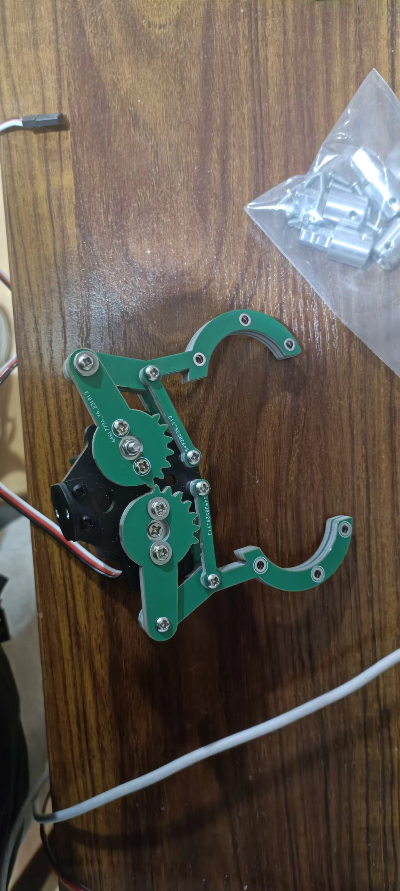
mechanical claw
Note! This project is only intended to provide a new approach; I do not recommend using this method as I have.
This project was created during my freshman year when I participated in the China Undergraduate Engineering Design Competition. Since I didn't know 3D modeling, but the competition required the use of a mechanical gripper I designed myself, I hastily decided to use JLCPCB to draw the mechanical gripper. Note: This project cannot fully construct a mechanical gripper; it requires the use of a commercially available mechanical gripper base (the black part in the image).
PDF_Mechanical Gripper.zip
Altium_mechanical claw.zip
PADS_Mechanical Gripper.zip
95182
Happy April Fool's Day! May you be a lucky fool!
JLCPCB Electronics' "Fool's Play Collection Campaign" - Keyboard for Senior Personnel...
Happy April Fool's Day! Can I steal your heart on April Fool's Day? JLCPCB Electronics' "April Fool's Day Fool's Challenge" features a specially designed keyboard for senior personnel. It includes Ctrl, Z, X, C, V, and S keys, as well as a POW (one-key shutdown keyboard). Senior personnel, especially senior software engineers, always copy and paste or cut and paste. When a problem occurs, they simply press Ctrl+Z to undo and start over. If they can't finish writing, they just shut down, go home, eat, and sleep, and try again the next day! Hehe~~ It also has a voice playback function, allowing you to save voice messages and play them upon power-on. You can confess your feelings to him/her on April Fool's Day! Hehehe~ Even if you fail, you can say April 1st is April Fool's Day~~~~ and still be friends~~~~~
e403efb9ec17f922aa057fda91cc78d0.mp4
Happy April Fool's Day! May you be a lucky fool. (PDF_Happy April Fool's Day!) .zip
Altium - Happy April Fool's Day! May you be a lucky fool. .zip
Happy April Fool's Day! May you be a lucky fool. .zip
Happy April Fool's Day! May you be a lucky fool. (.xlsx)
95183
electronic


 京公网安备 11010802033920号

 1410Y0500184MXRE03


