1. Project Function Introduction:
The CW32 voltage and current meter is an open-source hardware project designed to provide users with accurate voltage and current monitoring.
Combining ADC technology with circuit measurement principles, the digital voltage and current meter accurately converts analog voltage and current signals into digital displays, facilitating intuitive reading and analysis by electronic engineers. This device not only improves the accuracy and efficiency of circuit measurements but also helps engineers better understand circuit behavior, making it a powerful tool for electronic design and troubleshooting, playing a crucial supporting role in the work of electronic engineers. In product applications, the digital voltage and current meter ensures the accuracy and safety of circuit design while also providing strong support for product quality control and subsequent maintenance.
2. Project Highlights: The project
adopts a core board plus expansion board design concept, using plug-in components to simplify learning and deepen exploration.
The core board uses the domestically produced Wuhan Xinyuan Semiconductor CW32 as the main controller, while also being compatible with other similar development boards; however, the CW32 has advantages.
The project is highly comprehensive and practical, and after completion, it can be used as a desktop instrument.
The project offers abundant learning materials, including circuit design tutorials, PCB design, code programming learning, and training for engineers' debugging skills.
3. Demonstration:
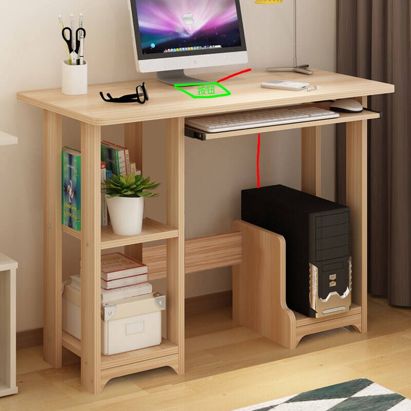
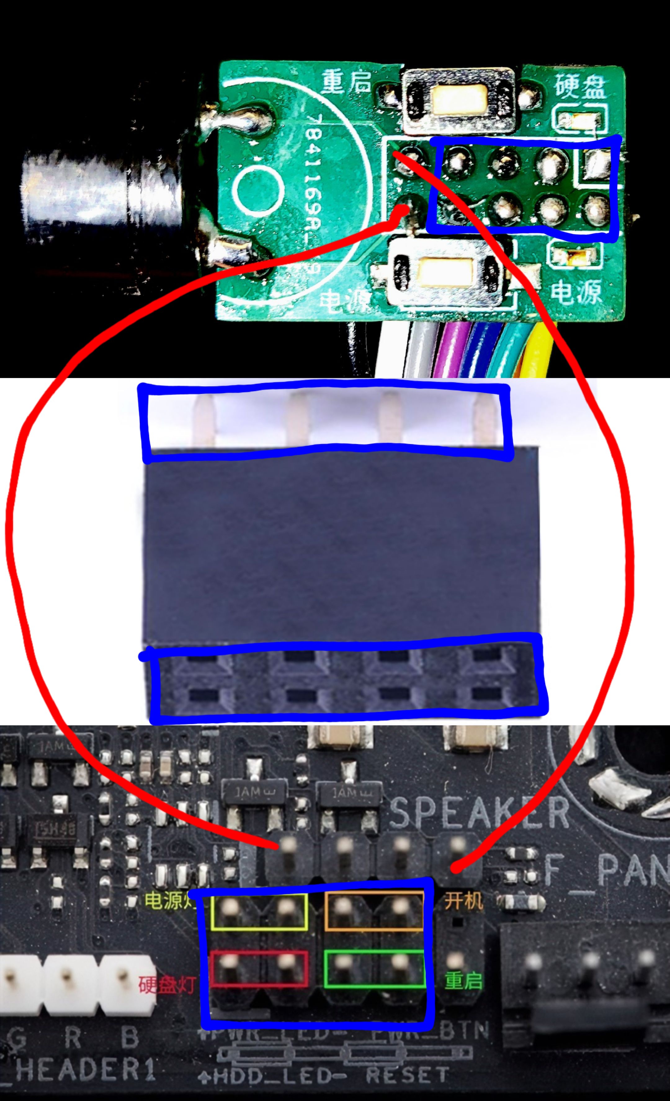
Computer front panel, restart and power buttons, power on and hard drive indicator lights
Computer front panel, restart and power buttons, power on and hard drive indicator lights
Applicable to: Desktop power buttons, open-frame cases, shoebox cases, damaged original panels, motherboard testing. Supports wired and wireless connections.
Wired connection:
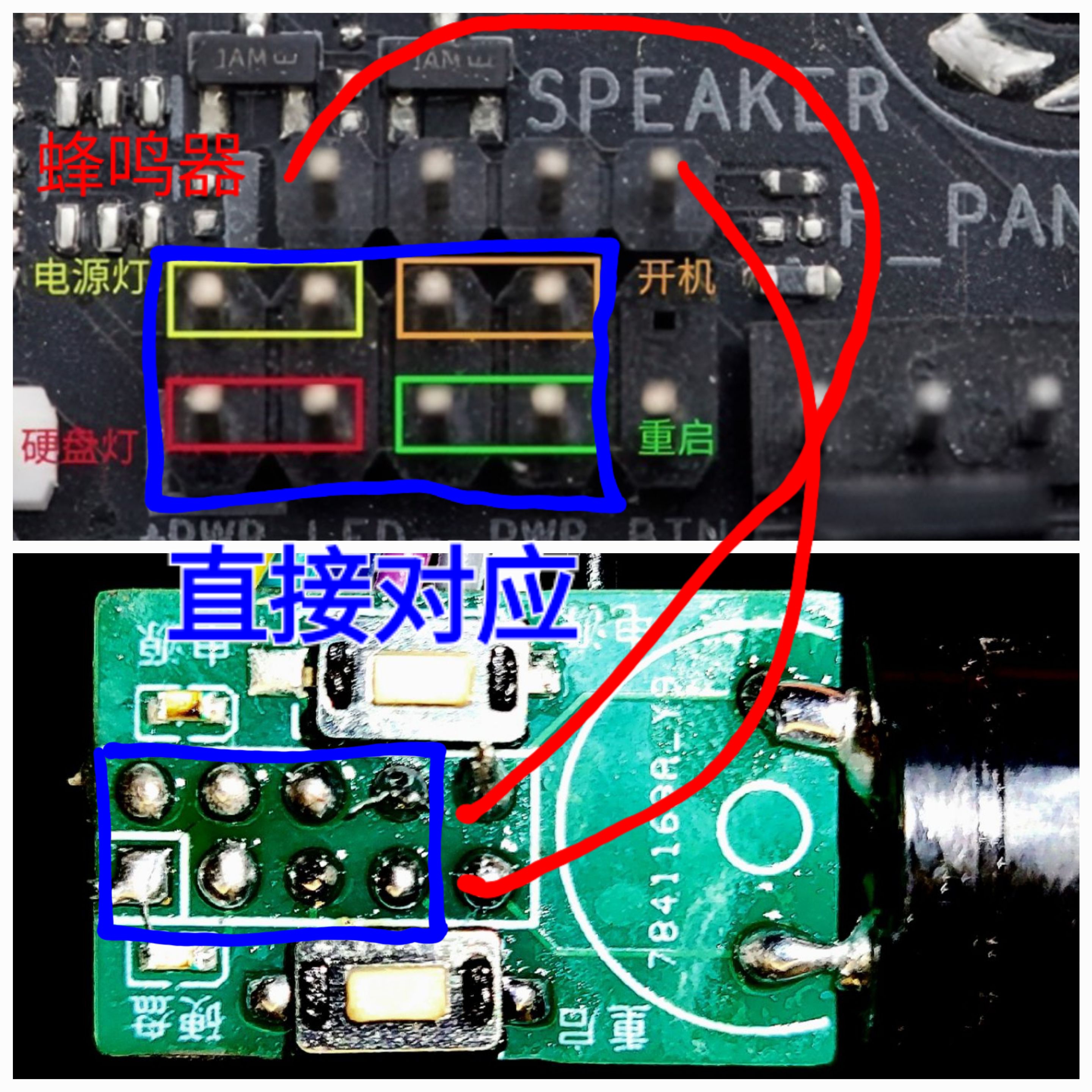

Wireless connection (actually, a short cable for the buzzer is also required):
studio_video_1724229728790.mp4
PDF_Computer Front Panel, Restart, Power Buttons, Power On, Hard Drive Indicator Lights.zip
Altium computer front panel, restart and power buttons, power on/hard drive indicator lights.zip
PADS_Computer Front Panel, Reset, Power Buttons, Power On, Hard Drive Indicator Lights.zip
BOM_Computer Front Panel, Restart, Power Buttons, Power On, Hard Drive Indicator Lights.xlsx
92979
Voltage and current meters based on LCSC GeoStar CW32F030C8T6 development board
This project is a voltage and current meter based on the LCSC CW32F030C8T6 development board. It uses the CW32's internal ADC 1.5V reference to acquire voltage and current data. The acquired results are then averaged and filtered before being displayed on a digital tube, thus completing a simple voltage and current measurement.
Preface:
This project is a replica of the voltmeter and ammeter project from the 2024 summer camp. I (the author) participated in this training camp during my summer vacation when I had some free time. Having only recently entered university, I know very little about hardware and lack the skills to modify the hardware schematics and PCB designs myself. Therefore, I can only replicate this project using a copy-paste method to enrich my knowledge of hardware design.

I. Project Introduction
This project is a voltmeter and ammeter based on the LCSC CW32F030C8T6 development board. It utilizes the CW32's internal ADC 1.5V reference to acquire voltage and current data. The acquired results are averaged and filtered before being displayed on a digital tube, completing a simple voltage and current measurement. Five modes can be used to calibrate the voltage and current for more accurate measurements.
II. Hardware Circuit
1. Overall Schematic Diagram

2. Main Control Chip and ADC Voltage and
Current Meter Acquisition Project directly utilizes LCSC's Diwenxing chip. The Diwenxing main control chip is the CW32F030C8T6 chip, which integrates a true 12-bit ADC successive approximation digital-to-analog converter with a resolution of 2^12. The ADC can use four channels: power supply voltage (VDDA), internal 1.5V reference, internal 2.5V reference, and external PB00 pin reference voltage (provided by TL431).

Voltage acquisition utilizes voltage and current division to measure voltage and current (acquisition range 0~30V).

Different voltage division ratios can change the measurement range, but higher voltage division ratios often lead to decreased accuracy. Therefore, selecting an appropriate voltage division ratio is essential.
Current acquisition uses a low-side current sampling circuit (acquisition range 0~3A).

The ADC cannot directly measure the current magnitude and can only sample it through a sampling resistor. The maximum current design is 3A. As for why it's 100mΩ... The author can only briefly explain that a 100 milliohm resistor has a small resistance and a small voltage drop. V = I * R = 3A * 0.1Ω = 0.3V, providing a sufficiently large voltage signal input to the ADC_IN12 for voltage detection, thus indirectly calculating the current. Furthermore, P = 3A² * 0.1Ω = 0.9W, indicating relatively low power consumption and preventing overheating. Regarding
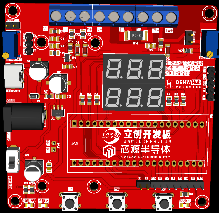
circuit board soldering and BOM materials
: since most components are through-hole, although the author lacks extensive soldering experience, the existing soldering iron was sufficient for soldering this circuit board. However, due to the small spacing between the TL431 holes, solder bridging was easy, resulting in one damaged board. A larger package of TL431 could be used; the author will not modify it further. Special reminder: Do not solder resistor R0 during the soldering process; solder it only after the experiment is complete.

The white digital tube is a 0.28-inch common anode white digital tube purchased from Taobao, but the BOM specifies a common cathode digital tube. Why would a mouse buy a common anode seven-segment display? Of course, it's to learn how to use a common anode seven-segment display (not really). The 2mm banana plug is a K2A33, which can be found by searching keywords. The rest were ordered from LCSC Mall based on the BOM. For detailed materials, please see the attached BOM.
Due to limited energy, I won't go into detail about other hardware circuits. If needed, you can refer to the official documents and videos below.
III. Software Program
The software used is Keil5. The software code is based on the program learning reference in the official training camp document (link). Based on the experimental case, the common cathode seven-segment display was changed to a common anode seven-segment display.
Common anode modification content. According to the principle of seven-segment displays, it is easy to know the difference between common anode and common cathode seven-segment displays (the common anode seven-segment display lights up when the anode is high and the cathode pin is low, while the common cathode is the opposite). We only need to change the encoding in Seg_Table[21] to the required common anode encoding table. Of course, you can also invert the original, but it is easy to get garbled characters. It is recommended to modify it according to the following figure. Then we set the GPIO pin of the digital tube's switch function to a high level, and finally set the GPIO of the common terminal initialization function Close_Com() to a low level, thus completing the modification of the common anode digital tube.

Regarding the modification of voltage and current calibration values, refer to the training camp video to modify or add a few common calibration values; I won't elaborate further.
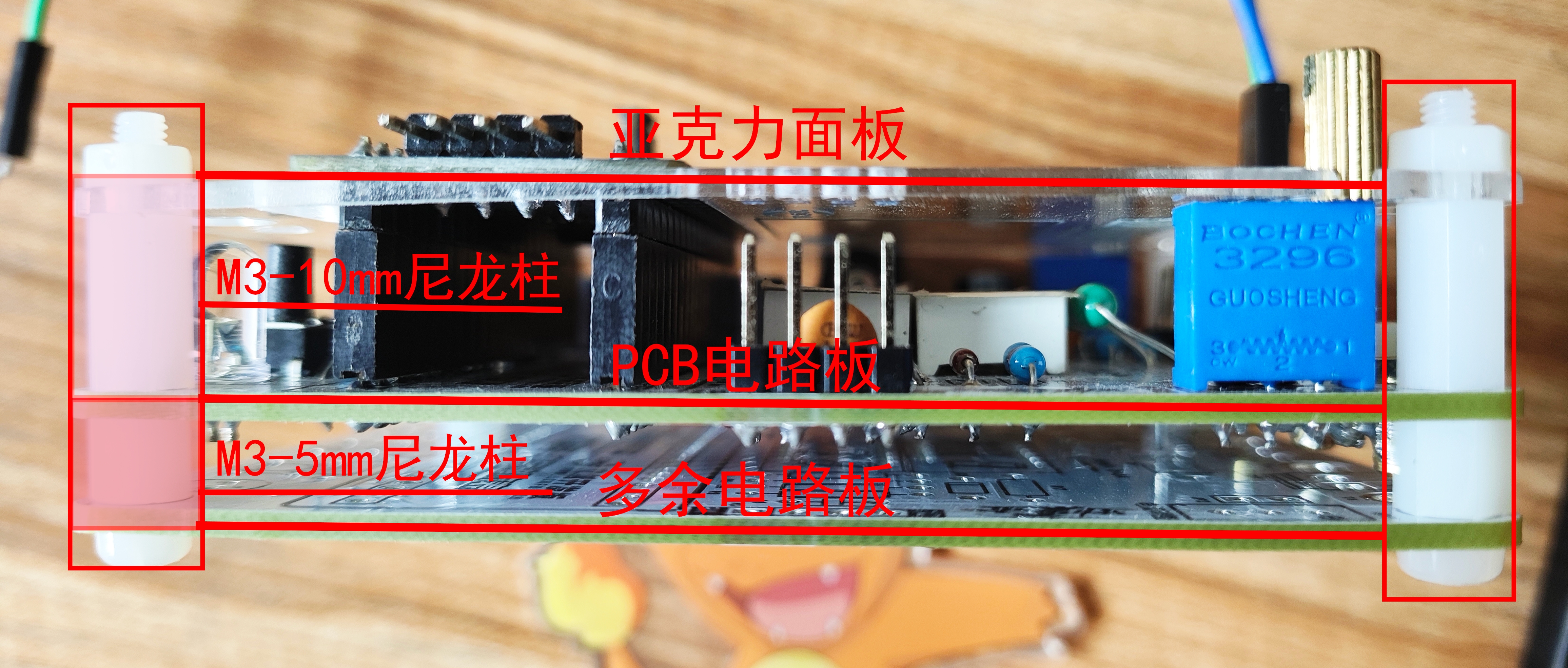
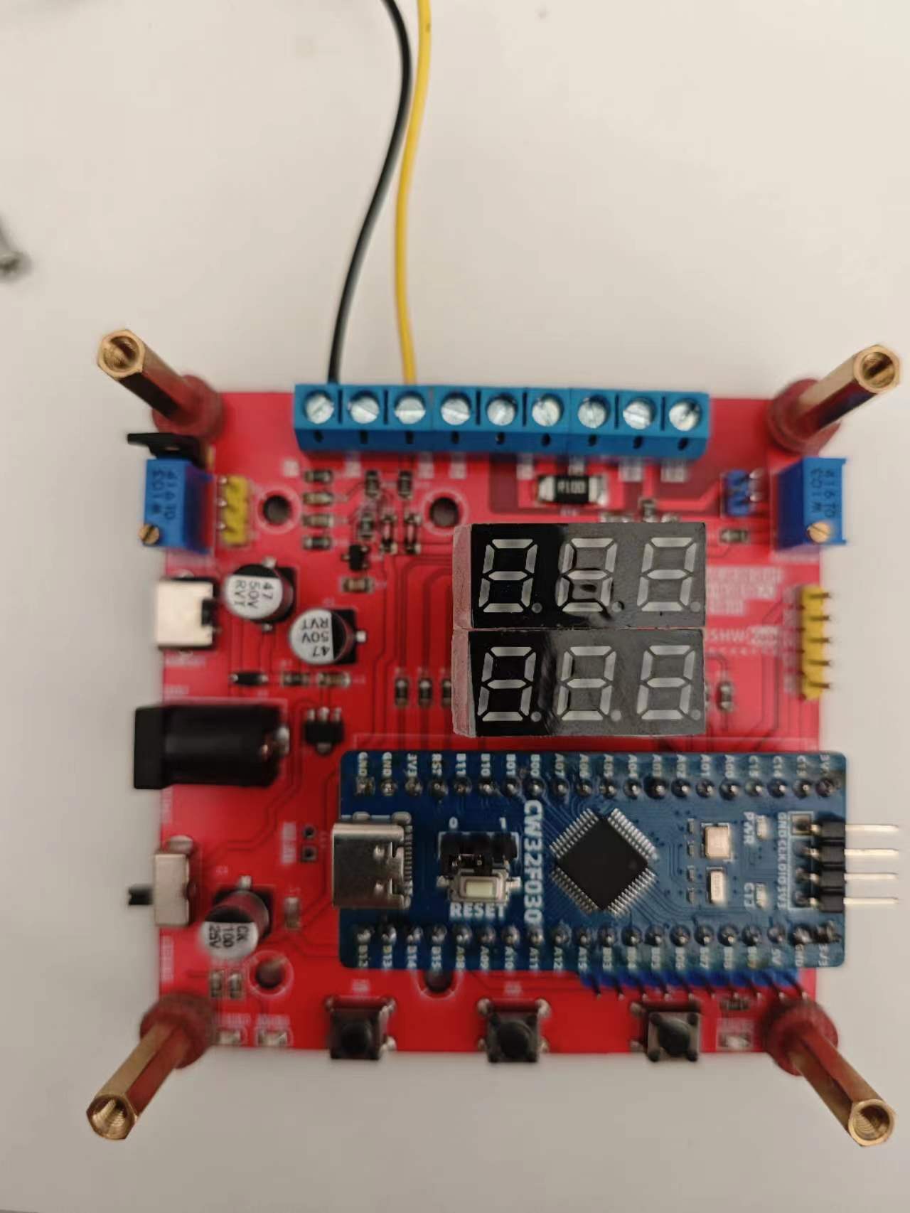
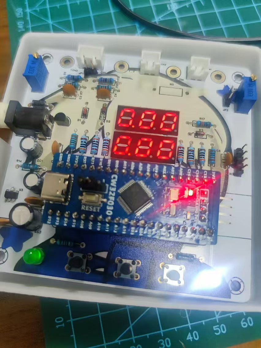
IV. Simple Assembly
After the PCB has been tested and found to be functional, you can use an extra circuit board as the bottom surface, connecting it with M3-5mm plastic copper pillars. On the front, use M3-10mm plastic copper pillars to connect the printed panel and secure it with screws and nuts.
The buttons cannot be directly pressed through the acrylic panel; you can modify them to 12mm or larger through-hole buttons. Alternatively, you can leave them as is and use a pen or similar object to press the buttons.
Finally, I'm glad you've patiently read this far, thank you for browsing. The above content is based on my personal understanding during my learning process. If there are any errors or inaccuracies, please point them out, and I will correct them promptly.
The demonstration video
is only a rough test and has a rough result because I don't have a multimeter right now. I can't verify its accuracy. I will complete the full test in a while.
Voltmeter and Ammeter Demonstration Video.mp4
BOM table.xlsx
PDF_Voltage and Current Meters Based on LCSC CW32F030C8T6 Development Board.zip
Altium-based voltage and current meter using the LCSC CW32F030C8T6 development board.zip
PADS - Voltage and Current Meter Based on LCSC CW32F030C8T6 Development Board.zip
BOM_Voltage and Current Meter Based on LCSC CW32F030C8T6 Development Board.xlsx
92980
CW32 Voltage and Current Meter
This is a voltage and current meter designed based on the LCSC GeoStar-CW32F030C8T6 development board.
1. Project Function Introduction:
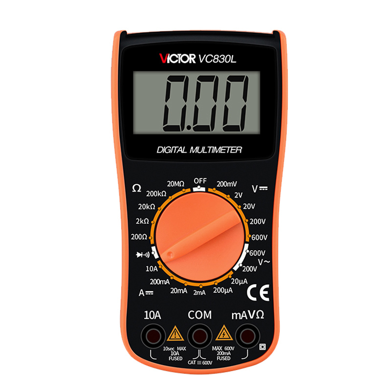
A traditional multimeter looks like this:
However, when participating in the LCSC training camp, we had a
LCSC CW32F030C8T6 development board.

We can use it to build a less traditional "voltmeter and ammeter".
2. Project Attributes: The main
controller comes from the LCSC CW32F030C8T6 development board.
I. Hardware Part:
Main Components:
1. Main Control Chip: CW32F030C8T6
Secondary Components:
1. Digital tube
2. LED
3. Potentiometer
4. Several capacitors and resistors
5. Several headers and pin headers
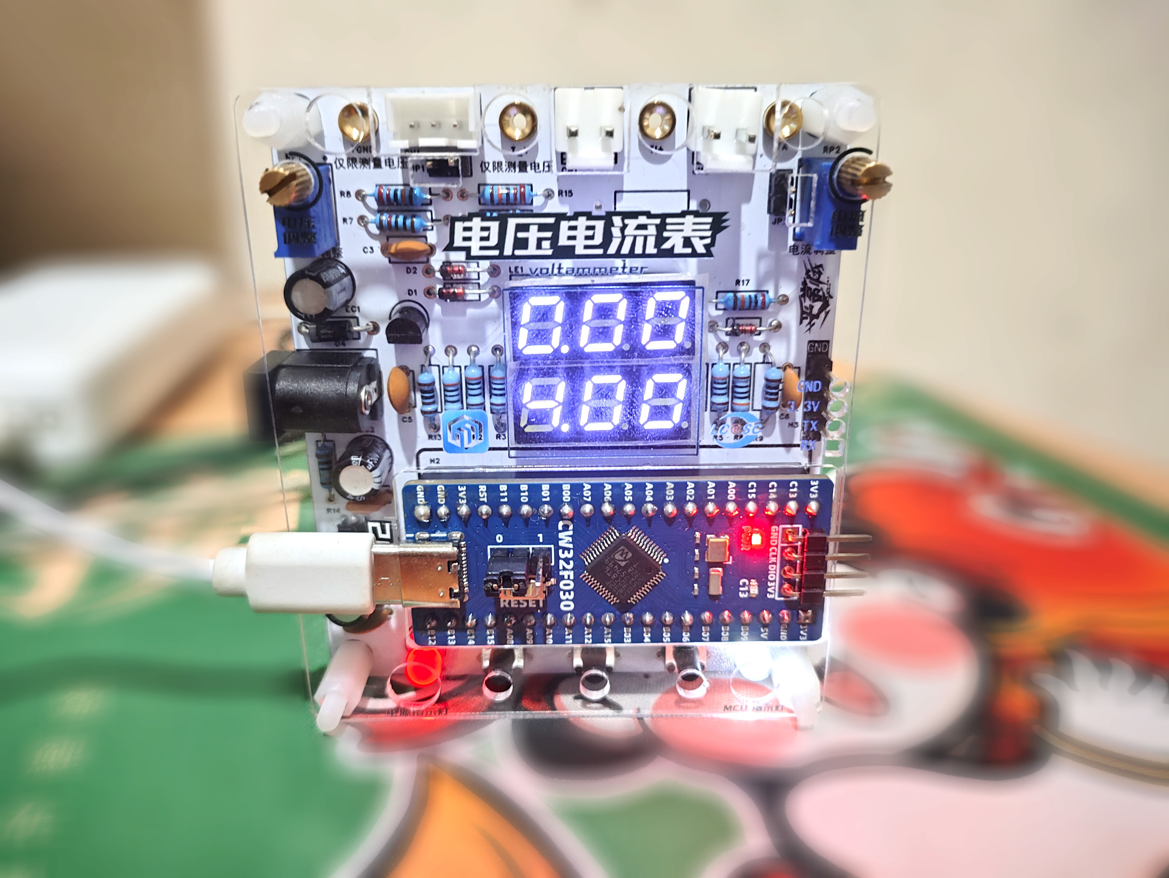
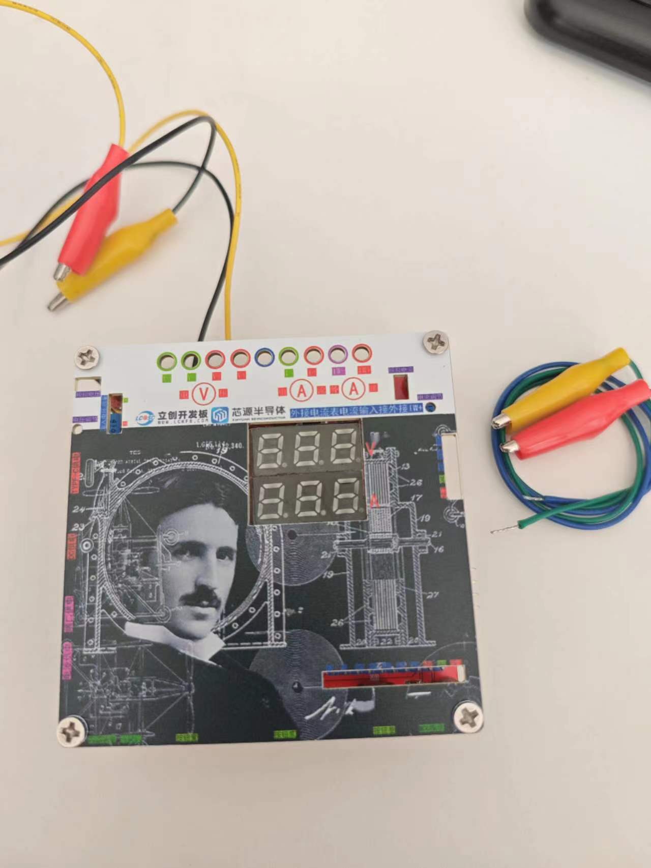
Appearance Display:
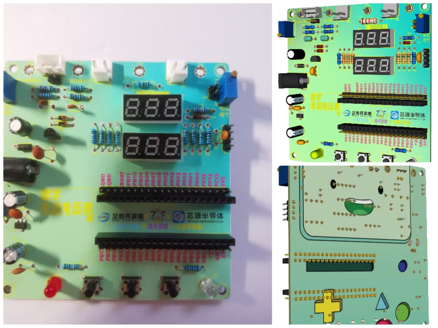
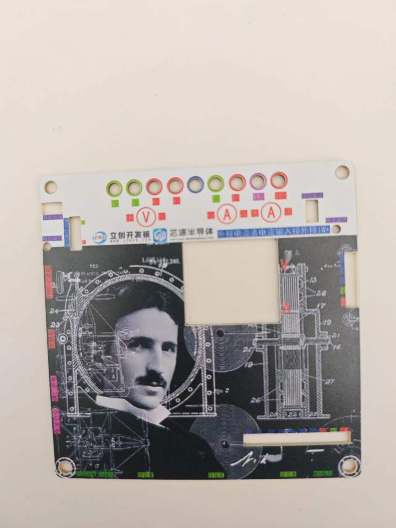
Design Panel Display:

Voltage Function Demonstration:
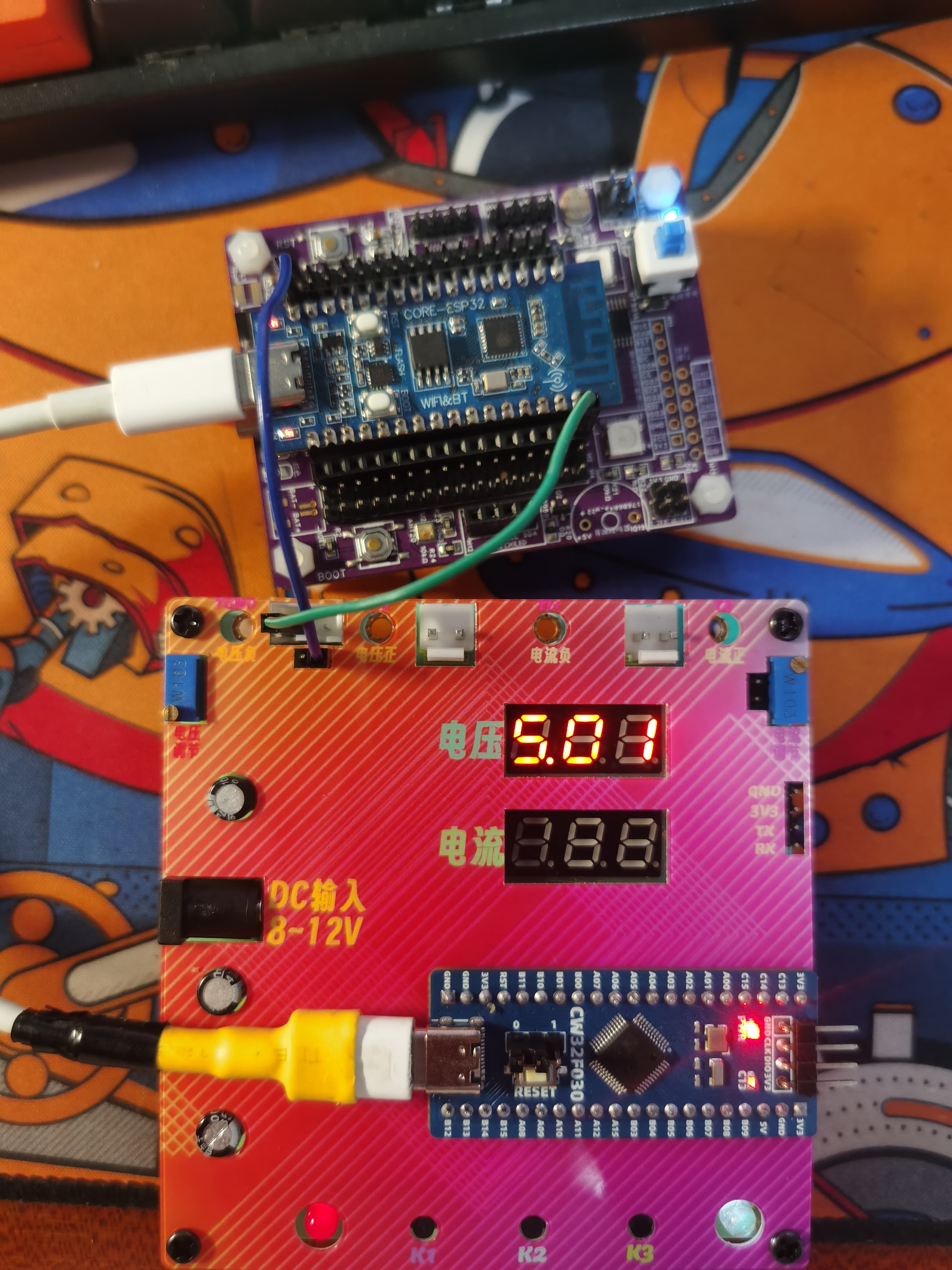
Measuring the 5V output of the ESP32-C3, it can be seen that there is almost no error.
II. Software Part
: The software part is written using Keil.
Keil is responsible for writing and modifying the code, and burning the code into the microcontroller chip
(code in attachment).
Quark Cloud Drive: Link: https://pan.quark.cn/s/4d8773ad9858 Extraction Code: GxBS
Code Description:
1. Already calibrated.
2. Includes calibration function: Press "K1" to calibrate.
3. Demonstration
in attachment.
PS: Due to file size requirements, for a better video,
please visit Bilibili: https://www.bilibili.com/video/BV1KzWbeVEgJ/
Ammeter and voltmeter project (1).rar
LCSC1.mp4
LCSC2.mp4
PDF_CW32 Voltage and Current Meter.zip
Altium_CW32 voltage and current meter.zip
PADS_CW32 Voltage and Current Meter.zip
BOM_CW32 Voltage and Current Meter.xlsx
92981
Current and voltage meters based on the CW32 microcontroller of the EarthStar platform
Diwenxing CW32 microcontroller current and voltage meter
I. Design Purpose and Background
1. To learn the concept, use and principle of ADC.
2. To learn the use and development of LCSC CW32F030C8T6.
3. After completion, it can be used as a daily tool.
II. Hardware Selection
1. The maximum input voltage of this project is as high as 30V, so the LDO is selected as SE8550K2 with a withstand voltage of 40V.
2. This project uses LCSC CW32F030C8T6 development board (core board) as the main controller.
The reasons are: (1) Wide operating voltage: 1.65V~5.5V.
(2) 12-bit high-speed ADC can reach ±1.0LSB INL 11.3ENOB multiple Vref reference voltages.
(3) It can directly drive digital tube display.
3. All resistors and capacitors in this project (except for current sampling) are 0805 packaged, and 1/8W power is sufficient. The current sampling resistor is 2512 packaged, with 3W power.
III. Main Circuits
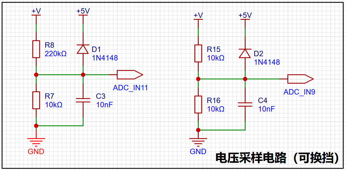
1. Voltage Sampling Circuit
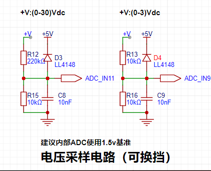
The maximum range of this project is designed to be 30V, and the ADC reference voltage is 1.5V. To reduce the power consumption of the sampling circuit, the low-voltage side resistor (R15) is selected as 10K.
Given the parameters, 1.5V/30V=0.05, and the high-side resistor is 10K/0.05=200K. A resistor slightly higher than the calculated value is selected as 220K.
The voltage divider resistor in this project is designed as 220K+10K, so the voltage division ratio is 22:1 (ADC_IN11).
An additional voltage sampling circuit is added to achieve range switching, and the voltage division ratio is 1:1 (ADC_IN9) below 3V.
This project uses diode clamping to ensure the safety of the MCU.
2. Current Sampling Circuit

The maximum current to be measured is 3A. It is not recommended that the voltage difference caused by the current sensing resistor exceed 0.5V.
Therefore, a 2512 package resistor is selected, and the corresponding current sensing resistor has a power rating of 3W and a current rise of 100mΩ.
According to the formula, 3A * 100mΩ = 300mV, 900mW can be calculated.
IV. PCB Design Knowledge Learned
1. Kelvin Connection of Current Sampling Resistor.

The Kelvin connection eliminates the influence of line resistance and contact resistance on the measurement results.
2. Silkscreen and Process.
Silkscreen printing on general PCBs is sprayed on, so when the font size is small and the line width is thick, it may become blurry, resulting in unclear markings.
It is recommended to choose the appropriate silkscreen font size and line width. Different silkscreen fonts also have different effects. Choosing a suitable font will result in better printing performance at the same line width and font size.
Inappropriate selection will cause the silkscreen to be illegible.
V. Software Code
. Since I had just learned about ADCs, I directly used Experiment Nine: Digital Voltage and Current Meter with Calibration Function.
Five working modes were defined. The K1 key is used to switch the display mode. The K2 key sets the parameter value for the corresponding mode and saves it to FLASH. The K3 key returns to mode 0.
Mode 0: Displays normal voltage and current values (the upper row of digital tubes displays the voltage value *.V or .*V automatically, the lower row displays the current value _.**A).
Mode 1: 5V voltage calibration setting. The upper row of digital tubes displays 5.05. The lower row displays the current voltage value _.V or ._V. In this mode, the multimeter should be set to 5.00V when measuring the measured bit. Pressing the K2 key will calibrate the current value to 5V.
Mode 2: 15V voltage calibration setting. The upper row of digital tubes displays 5.15. The lower row displays the current voltage value _.V or ._V. In this mode, the multimeter should be set to 15.0V when measuring the measured bit. Pressing the K2 key will calibrate the current value to 15V.
Mode 3: 0.5A current calibration setting. The upper row of digital tubes displays A.0.5. The lower row displays the current current value _.**A. Pressing the K2 key calibrates the current value to 0.5A.
Mode 4: Current 1.5A calibration setting. The upper row of digital tubes displays A.1.5. The lower row displays the current value *.**A. Pressing the K2 key calibrates the current value to 1.5A.
VI. Assembly Instructions:
The PCB component board and decorative cover are connected using M3 screws and M3-22MM hexagonal studs.
VII. Function Introduction:
This project can be powered by DC input and TYPE-C input, and an external power supply is also available with a reserved BAT interface.
When the input voltage measurement jumper is in the ON position, the supply voltage can be measured.
When the input voltage measurement jumper is in the OFF position and the analog voltage jumper is shorted, the variable analog voltage can be measured by adjusting the analog voltage potentiometer.
Shorting the analog current also allows for the measurement of variable current output using the analog current potentiometer.
Digital voltmeter and ammeter with calibration function.zip
Test video.mp4
PDF_Current and Voltage Meter Based on Divinity CW32 Microcontroller.zip
Altium-based current and voltage meter using the CW32 microcontroller.zip
PADS_Current and Voltage Meter Based on Divinity CW32 Microcontroller.zip
BOM_Current and Voltage Meter Based on Divinity CW32 Microcontroller.xlsx
92982
electronic
 software components use STLINK to program the official example code.


 京公网安备 11010802033920号

 TS80C52X2-MIKB


