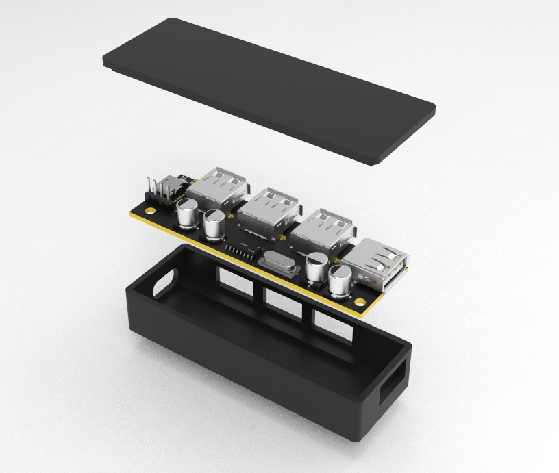
A USB 2.0 docking station based on SL2.1A has been verified. Using Type-C as input resolves the cable length issue. Due to a system reinstall on my computer, the shell modeling project,
preview are no longer available.
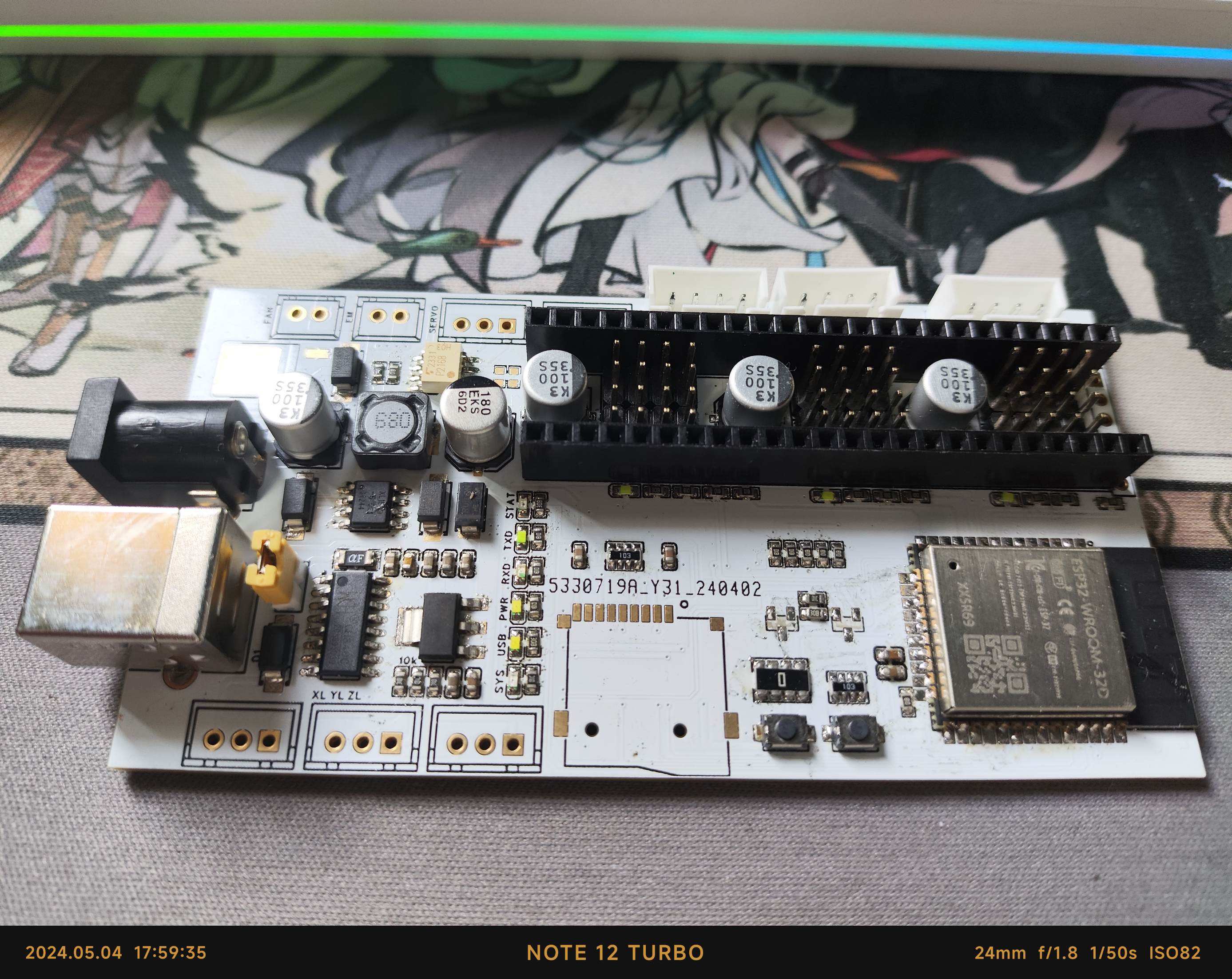
The board integrates a motor drive socket, a step-down module, and an ESP32 control module, intended for use as a writing machine control board. It also integrates PWM for servos and lasers, which can be modified as needed.
Under a 12V power supply, an ESP32 acts as the host computer, controlling the motor's movement. The Z-axis functions as a pen-lifting function for the motor, enabling drawing and writing effects.
Motion Control: The GRBL control board can control the X, Y, and Z axes, achieving precise position and speed control.
Status Feedback: The GRBL control board provides real-time feedback on the device's operating status, such as position, speed, acceleration, and load.
Multiple Command Support: GRBL supports multiple commands, including G-code, M-code, and T-code, enabling complex motion control and function settings.
Absolute and Incremental Encoder Support: GRBL supports input from both absolute and incremental encoders, enabling high-precision position control.
Stepper and Servo Motor Support: GRBL supports the control of stepper and servo motors, allowing for different motion control modes.
171162291.mp4
PDF_Laser Engraving Machine Motor Driver.zip
Altium_Laser Engraving Machine Motor Driver.zip
PADS_Laser Engraving Machine Motor Driver.zip
BOM_Laser Engraving Machine Motor Drive.xlsx
94363
STM32G030F6P6 Minimum System Board
STM32G030F6P6 Ultra-small size minimum system board
I recently got a few STM32G030F6P6 chips from a Taobao special offer, so I designed a small core board for fun. I referenced the layout of https://oshwhub.com/duya25446/stm32g0, but made significant modifications to the lead-out section (mainly for easier routing). I added a BOOT button for easy programming with a USB-to-serial module. I also added two 5.1k resistors for the Type-C interface, allowing for power supply with a C-to-C charger. The LDO was replaced with a higher current ME6211 for easier screen display.
PDF_STM32G030F6P6 Minimum System Board.zip
Altium_STM32G030F6P6 Minimum System Board.zip
PADS_STM32G030F6P6 Minimum System Board.zip
BOM_STM32G030F6P6 Minimum System Board.xlsx
94364
Based on SW3538 fast charging protocol module, dual-port 60W
Fast charging modules are suitable for use in vehicles; SW3538 and SW3518 have universal pin configurations.
Based on modifications to this project (https://oshwhub.com/tnanastar/sw3556-140w-geng-huan-mos)
, copying it once was successful. The original version, while having two charging ports, couldn't fast charge simultaneously.
I tested it on an iPhone, and the maximum power was 25W.
It's suitable for keeping in the car; a cigarette lighter to DC adapter would suffice.
PDF_Dual-port 60W fast charging module based on SW3538 fast charging protocol.zip
Altium_Dual-Port 60W Fast Charging Module Based on SW3538 Fast Charging Protocol.zip
PADS_Dual-Port 60W Fast Charging Module Based on SW3538 Fast Charging Protocol.zip
BOM_Based on SW3538 Fast Charging Protocol Module Dual Port 60W.xlsx
94365
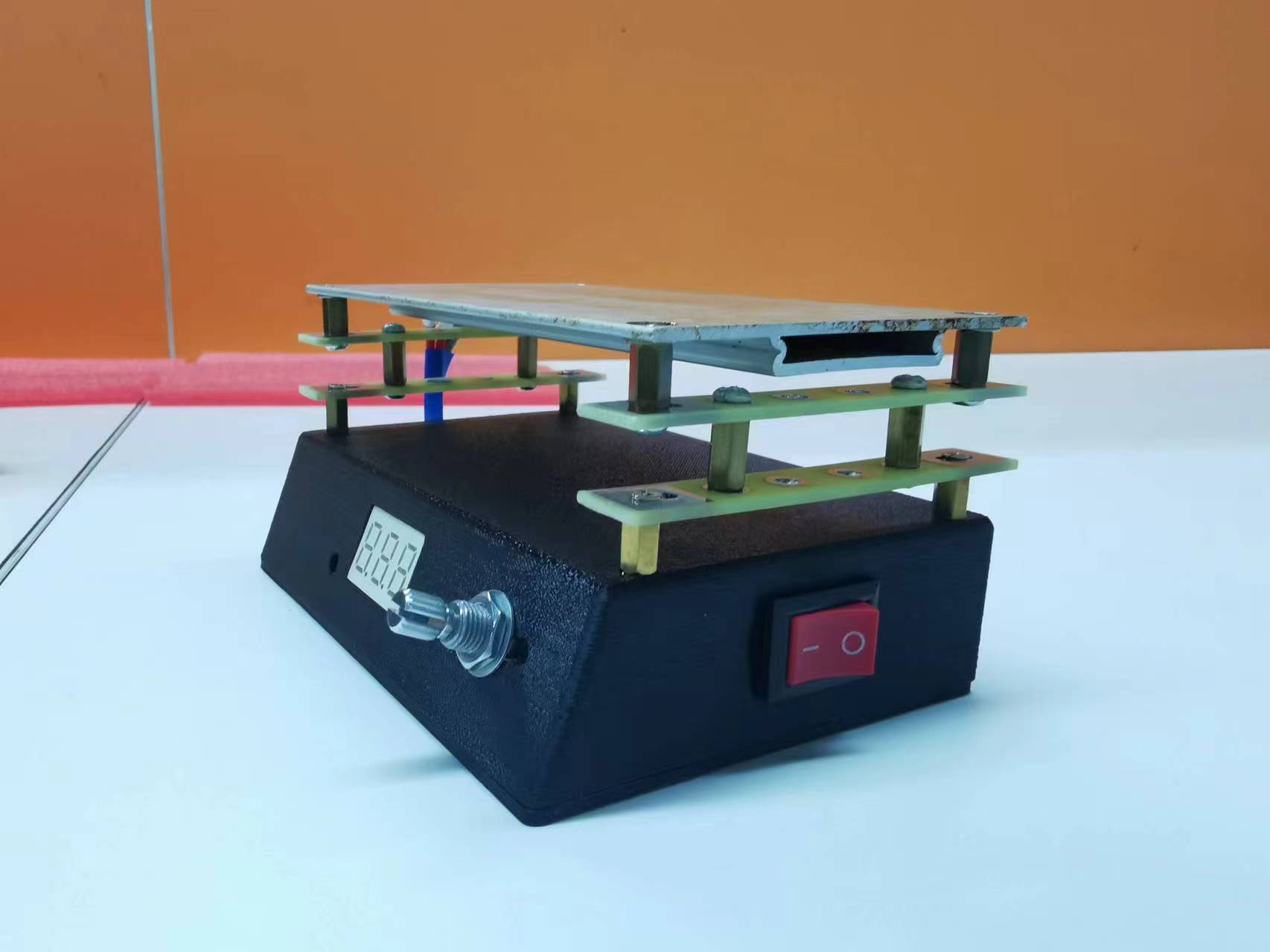
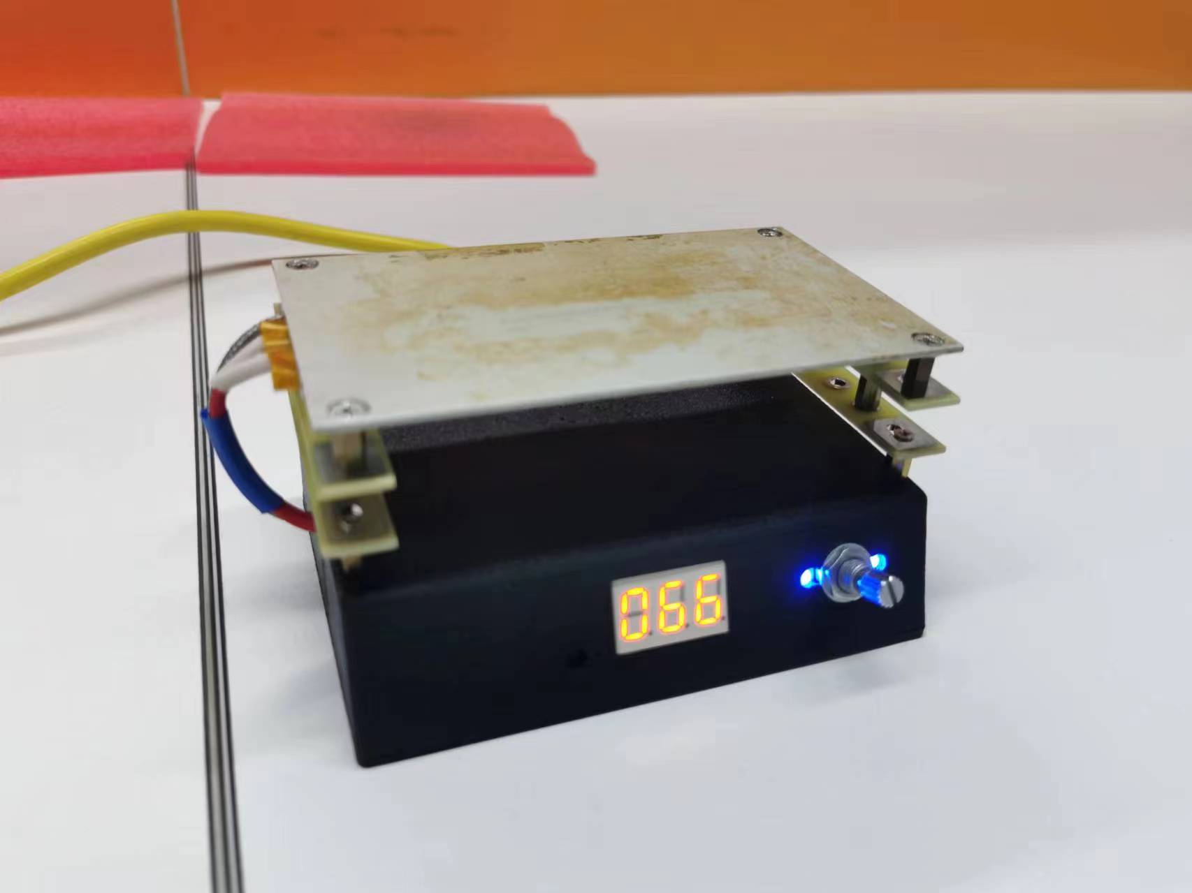
DIY heating table
DIY Heating Platform Mass Production Plan (by Finding a Sheep Expert)
DIY Heating Platform Mass Production Plan by Sheep (a popular tech blogger):
https://oshwhub.com/sheep_finder/pcb-heng-wen-jia-re-tai!
Heat-resistant tape was applied to the heating platform to prevent stains from being difficult to clean during use. Inspired by other projects, heat-insulating pads were added under the copper pillars to reduce heat conduction downwards and increase the lifespan of the resin casing.
![c781dcbd8bd6f82f9672e8a4bda0d57.jpg]

![62e7d8899e42537627476f1b875d851.jpg]
Heating platform demonstration.mp4
Heating process demonstration.mp4
PDF_DIY Heating Table.zip
Altium_DIY Heating Table.zip
PADS_DIY Heating Table.zip
BOM_DIY Heating Platform.xlsx
94366
The CT7601 has a 192kHz USB interface and supports recording.
It uses the CT7601SR chip, with a 192kHz 32-bit DAC I2S output and a 192kHz 32-bit ADC I2S input. For firmware installation, please refer to the design documentation (see the compressed file).
Using the CT7601SR chip, it has a 192kHz 32-bit DAC I2S output and a 192kHz 32-bit ADC I2S input.
CT7601 Interface Data and Firmware.zip
PDF_CT7601 USB 192kHz interface, supports recording.zip
Altium_CT7601 USB 192kHz interface, supports recording.zip
PADS_CT7601 USB 192kHz interface, supports recording.zip
BOM_CT7601 USB 192kHz interface, supports recording.xlsx
94367
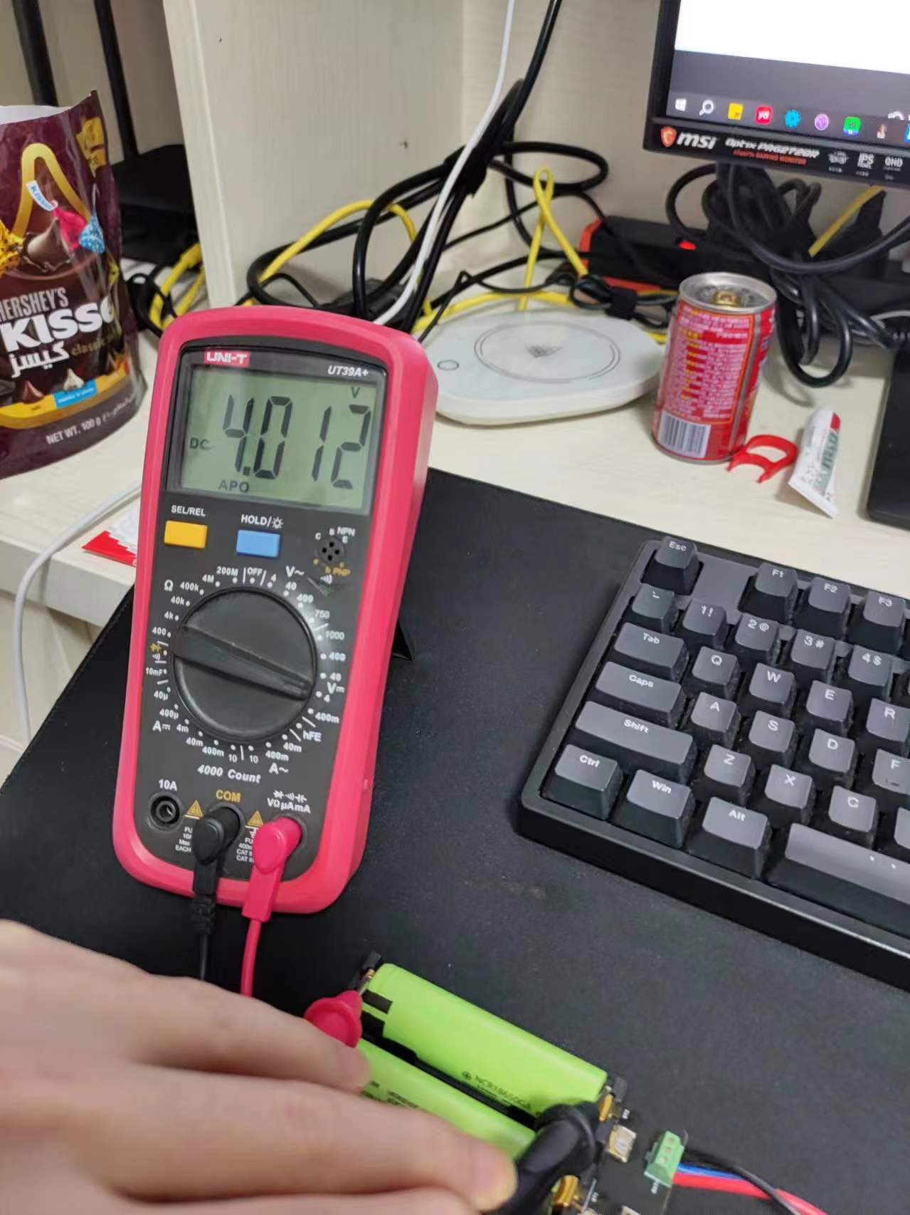
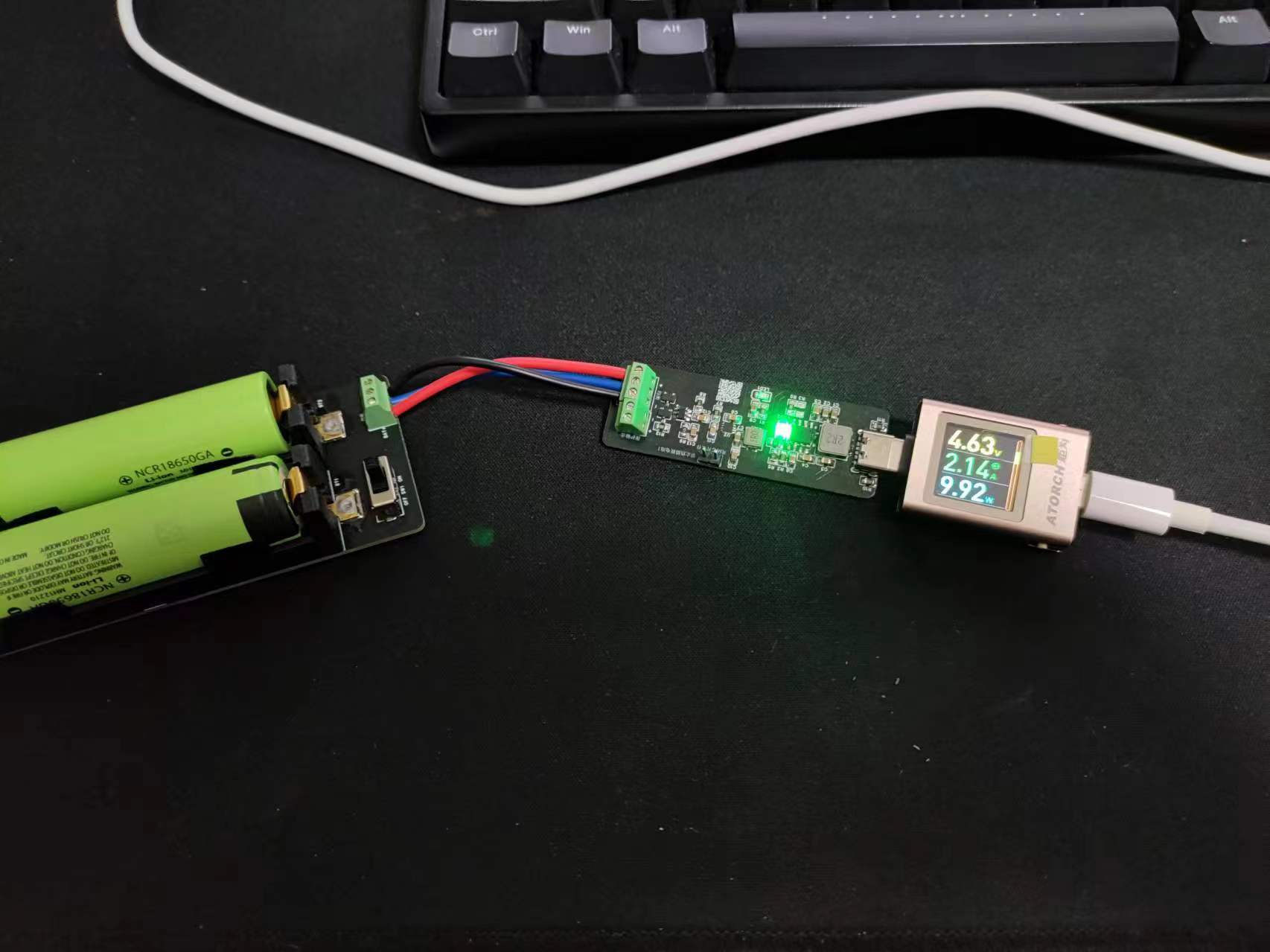
Snowflake light base (rechargeable)
This snowflake light base, powered by a 3.7V lithium battery, is very convenient and attractive. Come and recreate it!
Update Log
June 7, 2024 First Update:
This update improves the 3D printed base shell. It no longer uses two plates joined together or has a hollow design, resulting in a more aesthetically pleasing appearance. The 3D shell file is attached. The Type-C male connector has also been updated. Feedback indicated that the previous version's Type-C male connector was not sturdy and easily damaged. This update resolves this issue with a new, more robust Type-C male connector. The link to the new Type-C male connector is also updated below. See the following images for the updated base:
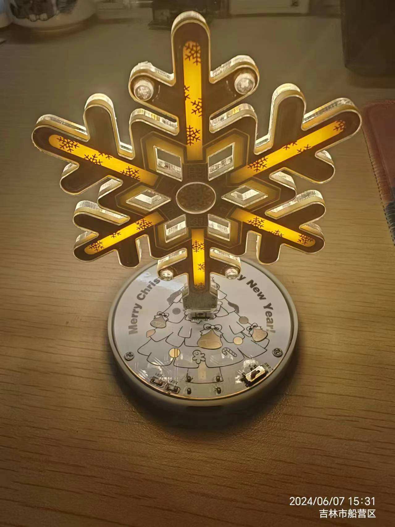
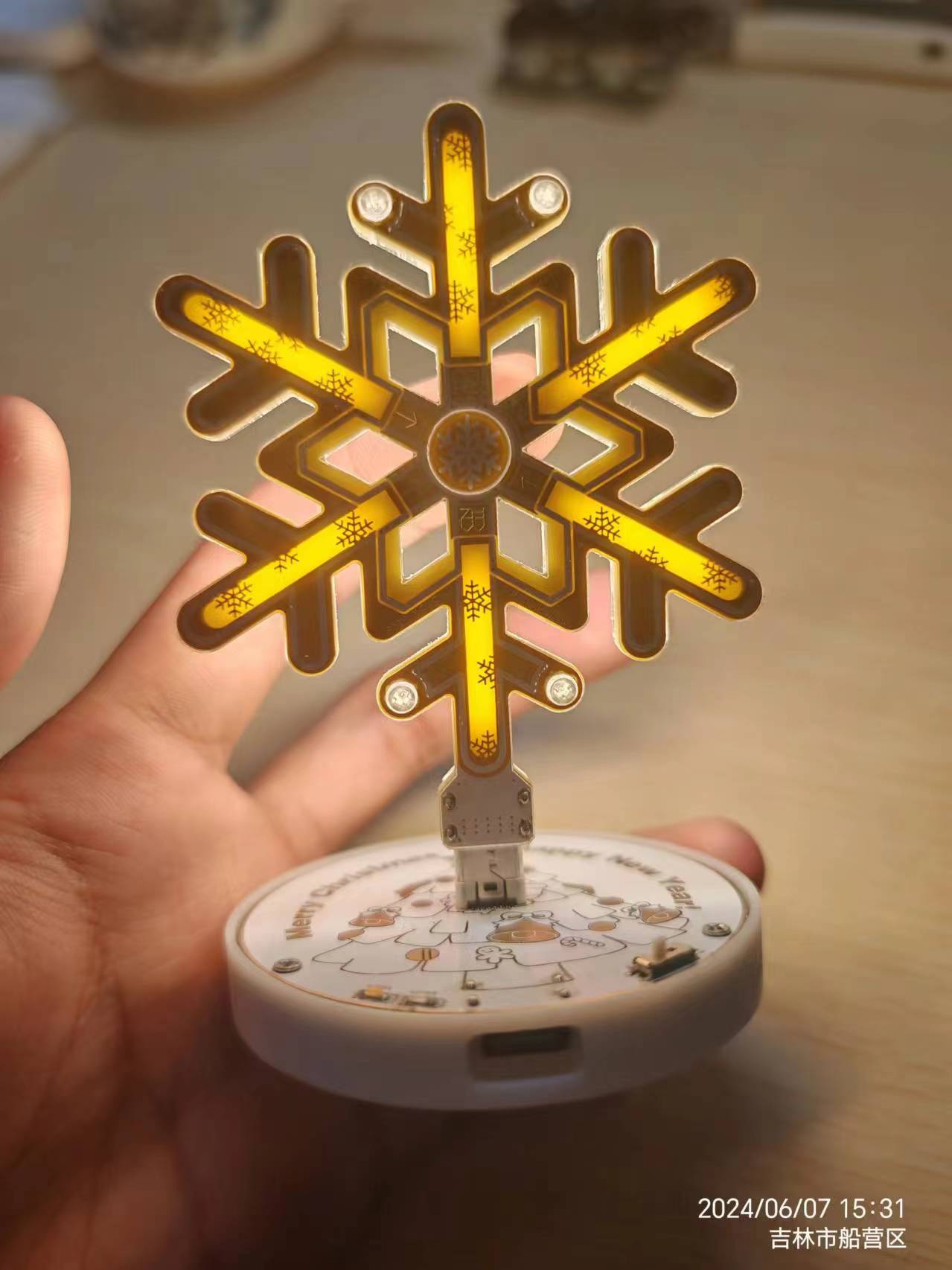
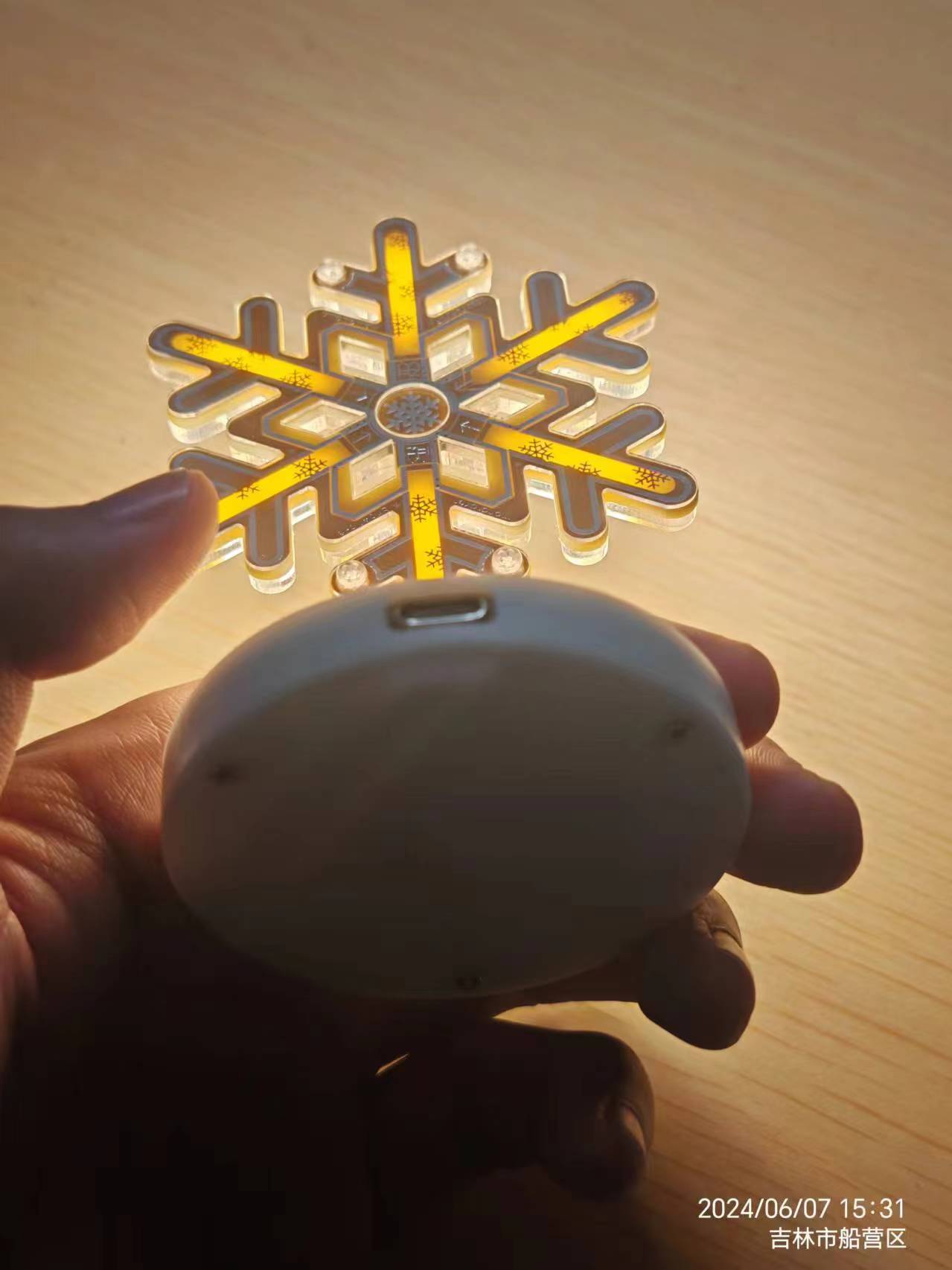
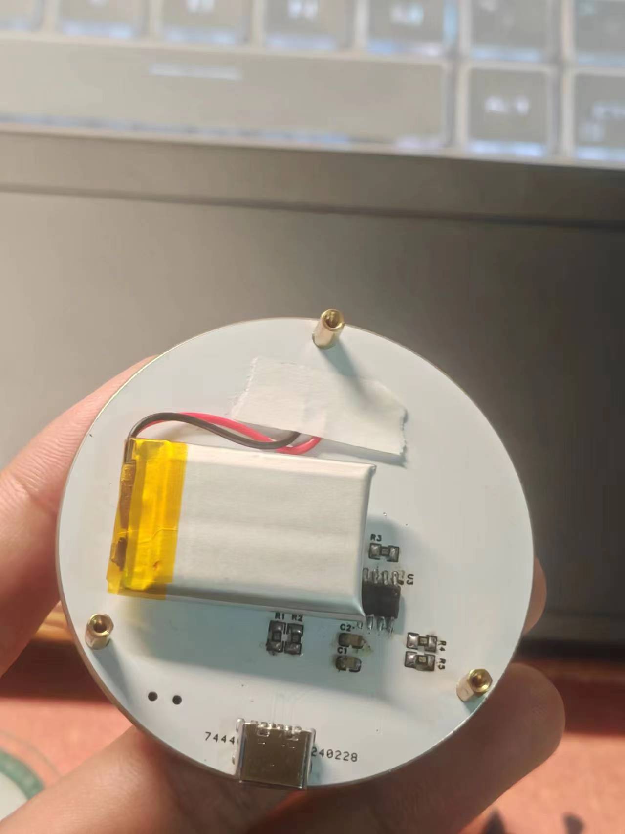
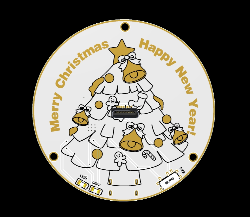
The snowflake lamp designed by mondraker is irresistible, but it's very inconvenient to use without a base. I've seen bases powered by power cords before, but those weren't very convenient either. The snowflake LED normally requires a 5V power supply, but I found that it also works fine with a 3.7V lithium battery. Therefore, I simply used the TP4056 power management chip with the lithium battery, eliminating the need for an additional boost circuit or power supply chip. Only a few resistors and capacitors are needed, making it very cost-effective. Here are some of the component links for
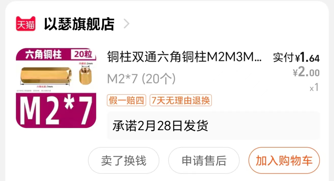
the snowflake LED : Vertical SMD switch: https://m.tb.cn/h.5E6ARwQpmphfHLR?tk=hxHBWmFJvMm Vertical Type-C male 16-pin: https://m.tb.cn/h.gVAhPS9uDgR4bxS?tk=WLOqWxy7UuC HU7632 Type-C female 6-pin: https://m.tb.cn/h.5vGgUaqWshhJkdm?tk=AVdYWmFHyaz TP4056 chip: https://m.tb.cn/h.5wOyYIYXlGUVj0g?tk=Kc9qWmFIQ0o 200mAh 3.7V lithium battery: https://m.tb.cn/h.5EhblcgOavtK02a?tk=olUEWmFsLqt Resistors, capacitors, and LEDs are all 0805 packages; you can choose whichever you prefer, but we highly recommend purchasing from the store below. M2 screws: Buy M2x4 size. Copper pillars should be purchased according to the battery size; this is for reference only. Assembly: The upper board is soldered; the lower board does not need soldering. Simply connect the upper and lower boards using copper pillars and screws. The battery can be soldered directly (pay attention to the positive and negative terminals!). For detailed video, please visit: https://b23.tv/QVYSwJF


WeChat_20240309080027.mp4
3DShell_3DShell_Base PCB_B.stl
PDF_Snowflake Light Base (Rechargeable).zip
Altium Snowflake Light Base (Rechargeable).zip
PADS Snowflake Light Base (Rechargeable).zip
BOM_Snowflake Light Base (Rechargeable).xlsx
94368
Simple and controllable heating table - easy
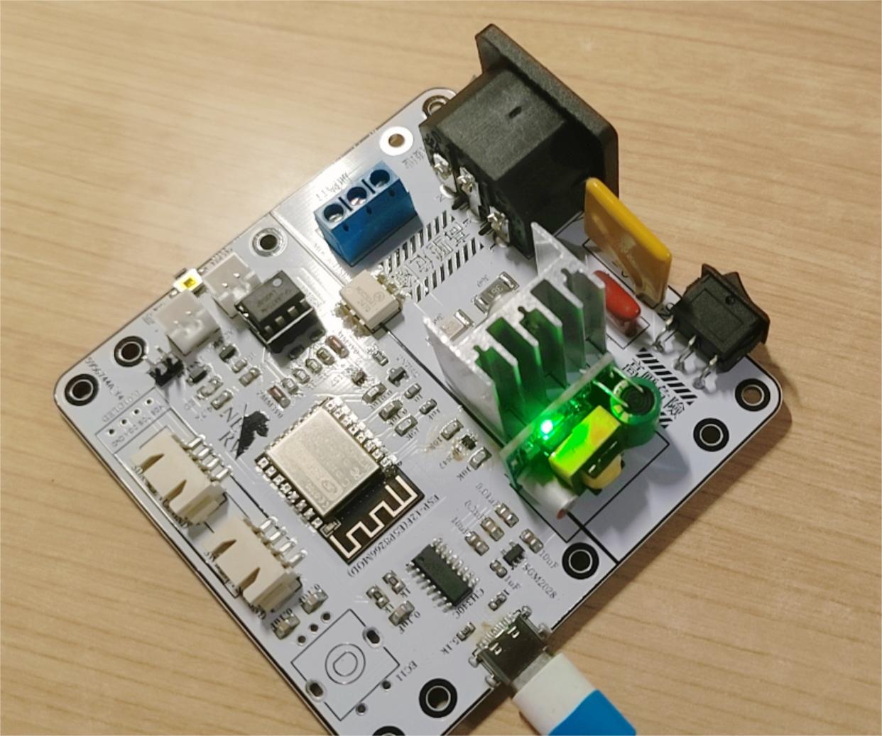
A simple, controllable PTC heating platform.
Slowly evolving and being updated.
Modified from a simple, practical, and low-cost heated BGA soldering station,
with added POWER indicator light.
An mounting edge has also been added. One board is all you need for one machine.
PDF_Simple Controllable Heating Table - easy.zip
Altium Simple Controllable Heating Table - easy.zip
PADS_Easy Controllable Heating Table - easy.zip
BOM_Simple Controllable Heating Table-easy.xlsx
94369
electronic
 *****
*****  *****
*****  *****
***** 
 preview are no longer available.


 京公网安备 11010802033920号

 TMP82C255AF-10


