 It
It 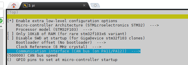 Select the "Communication interface" column according to your needs (the figure shows CAN communication; when selecting USB, the pins are also selected as PA11/PA12). The CAN rate must be consistent with the host computer settings. When using USB, the USB baud rate in printer.cfg remains unchanged by default.
  When using CAN connection, connect the motherboard power supply jumper cap shown in the diagram. When using USB connection, disconnect the jumper and power the core board via USB.
 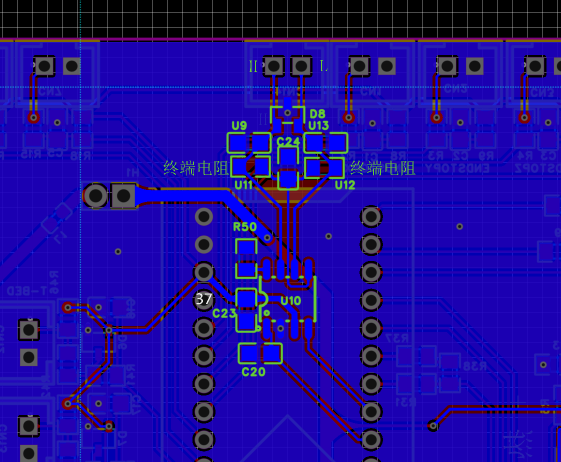 If a CAN transceiver is used, the terminating resistors U11 and U12 need to be selected according to the CAN bus connection. This design uses split terminating resistors, selecting two 60Ω or 1.3kΩ resistors (similar values are acceptable, such as 62Ω and 1.37kΩ), so that after the CAN bus connection is completed, the resistance between the H and L sides of the bus should be around 60Ω when measured with a multimeter. Resistor R50 is used to set the transceiver to work in slope mode, reducing speed and interference. If not needed, it can be removed and directly shorted to ground. Filter capacitors C20, U9, and U13 may need to be selected with a smaller value or removed depending on the communication speed.
  ----------------------------------------------------------------------------------------------------------------------------
All reference designs on this site are sourced from major semiconductor manufacturers or collected online for learning and research. The copyright belongs to the semiconductor manufacturer or the original author. If you believe that the reference design of this site infringes upon your relevant rights and interests, please send us a rights notice. As a neutral platform service provider, we will take measures to delete the relevant content in accordance with relevant laws after receiving the relevant notice from the rights holder. Please send relevant notifications to email: bbs_service@eeworld.com.cn.
It is your responsibility to test the circuit yourself and determine its suitability for you. EEWorld will not be liable for direct, indirect, special, incidental, consequential or punitive damages arising from any cause or anything connected to any reference design used.
Supported by EEWorld Datasheet
EEWorld
subscription
account

EEWorld
service
account

Automotive
development
community

Robot
development
community

About Us Customer Service Contact Information Datasheet Sitemap LatestNews


Room 1530, 15th Floor, Building B,
No.18 Zhongguancun Street,
Haidian District,
Beijing, Postal Code: 100190
China
Telephone: 008610 8235 0740
 京公网安备 11010802033920号

 1200DGH500822JB


