The process of building
my own mini phone was a completely new experience for a novice like me. From drawing the adapter board circuit diagram, designing the PCB, and soldering components, to flashing the Taishanpai system, driving the 3.1-inch screen, configuring the compilation environment, compiling the system, and using Linux commands, I learned all of this step-by-step through video tutorials and documentation. The following points will illustrate this process and summarize the problems encountered:
Circuit Design:
1. Designing a conversion board for a MIPI screen + touch interface on two lanes.
This circuit design is not difficult; it simply involves using differential equal lengths for the two sets of signals. I learned the importance of equal lengths in high-speed signal PCB design.
My differential equal lengths are a bit ugly, as shown in the picture.

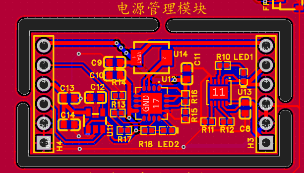
2. Designing a power module for battery power.
A phone without a battery is incomplete. I referenced Zhihui's power module. However, his boost chip is hard to find, so I didn't include the component here and didn't use battery power. I need to find a more cost-effective power module later. This power module can be removed from the board and used independently. Board within a board, haha...
3. Use the connectors to bring out the speaker and microphone.
4. Add a camera. Add the camera recommended by Engineer Wu. With a camera, it's more like a mobile phone, right! With a camera, you can create more interesting projects, such as completing an AI image recognition project using OpenCV.

Purchase link: https://item.taobao.com/item.htm?_u=kqm6hj0b32&id=690216988471&spm=a1z09.2.0.0.37802e8d1IVtvE
Circuit soldering:
The design of this small mobile phone adapter board is not difficult. The key difficulty is soldering the 31P-0.3 FPC connector. This connector is not easy to solder with a soldering iron. It is best to use medium-temperature solder paste and a soldering station, which is easier. Use an electronic magnifying glass and a multimeter with a fine tip to check the soldering of the connector. I personally think it is easier to solder with a soldering station.
Engineer Wu also released a detailed video.
Video link: 【【Linux Mobile Phone Soldering and Debugging】LCSC Taishanpai RK3566 Linux Development Board Training Camp Lesson 9】 https://www.bilibili.com/video/BV19i421y7Hv/?share_source=copy_web&vd_source=c4ac3c1e03440fed67ffc76ecb6d23d1
3D Printed Shell:
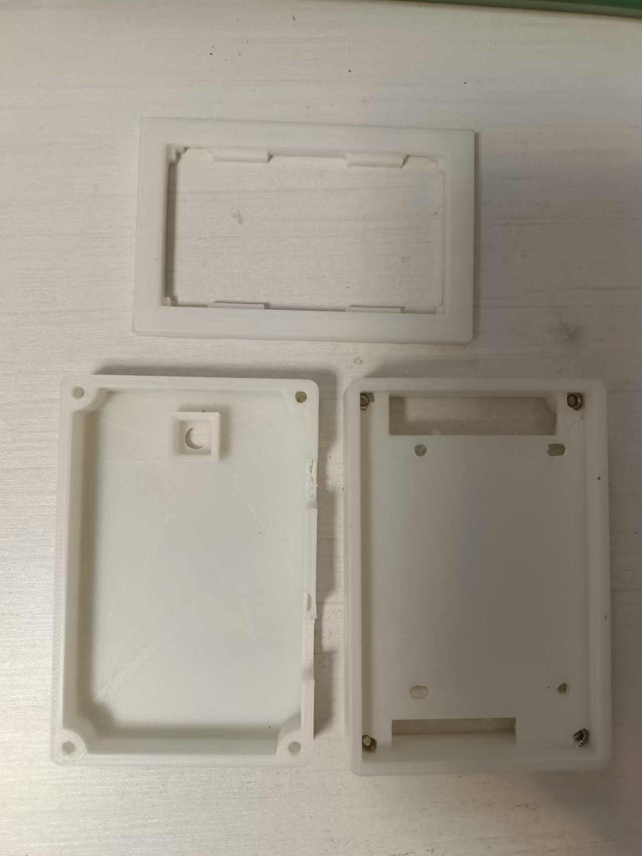
Because the PCB design didn't center the 3.1-inch screen's FPC mount, the screen was offset by 4.8mm. To center the screen, the phone shell had to be enlarged, turning the "fat" phone into a "chubby" one. The camera position was designed below the screen; it should have been above the screen, which was also a minor issue. The 3D shell uses SW design. It consists of three parts: the top shell, the bottom shell, and the screen frame. The screen frame is to hold the screws underneath. (See diagram).
Phone System Selection:
The phone must use the Android system. The system flashing and compilation will not be described here, as Mr. Wu's videos and documentation explain it very clearly.
Documentation link: https://lceda001.feishu.cn/wiki/M1DVwL6HgihWzlkKgmucPbDbnG4
Video link: https://www.bilibili.com/video/BV1QT4m1S7Ae/?spm_id_from=333.788&vd_source=11a361314ce81edd5129af7fd3ef9b2c
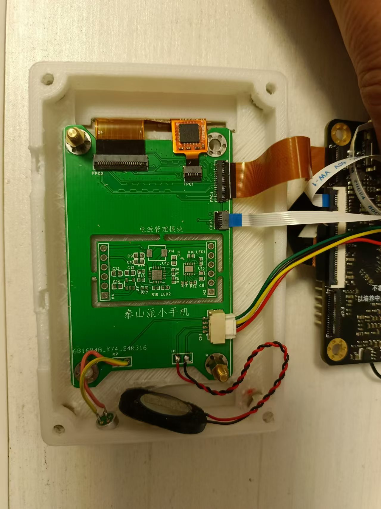
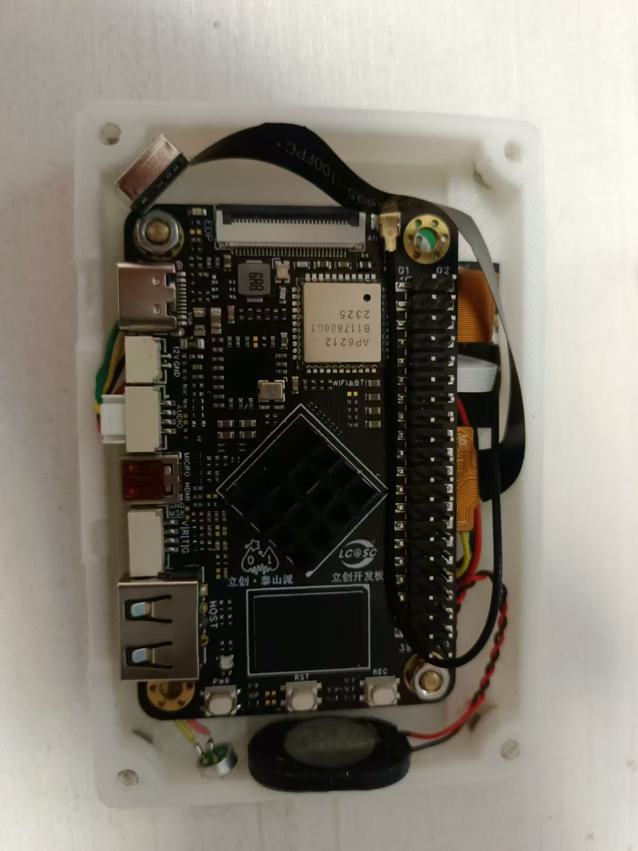
Internal image display:
Video display:
https://www.bilibili.com/video/BV1Ys42137gF/?share_source=copy_web&vd_source=c4ac3c1e03440fed67ffc76ecb6d23d1
Attachment notes:
The Boot file is adapted to the baseboard's gigabit network card and USB hub. The 3D printed parts are not yet fully complete. I won't upload it. I'll just show you a replica of the base plate.


 京公网安备 11010802033920号

 JAN1N759BTR


