I found a nice-looking amplifier casing on Taobao, and my study was missing a small amplifier.
So I decided to make a desktop amplifier for my study.
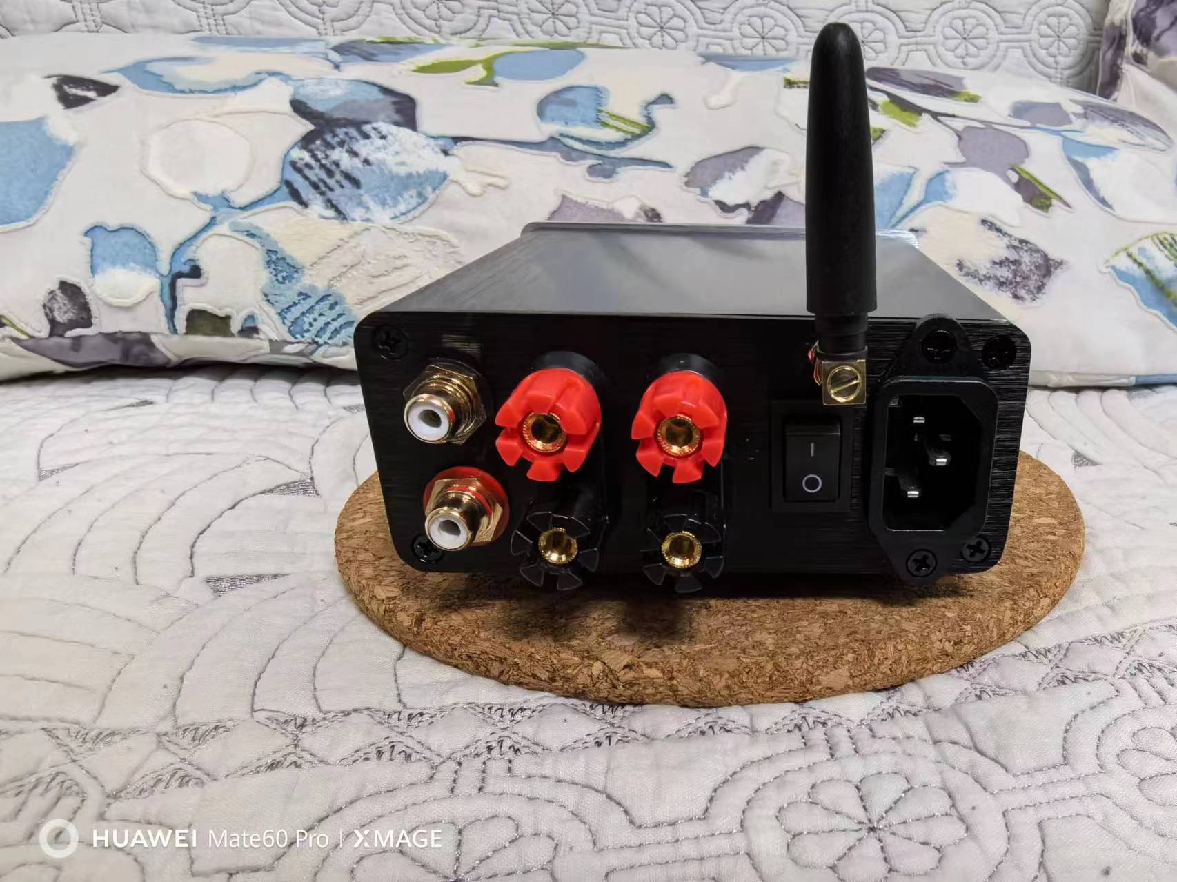
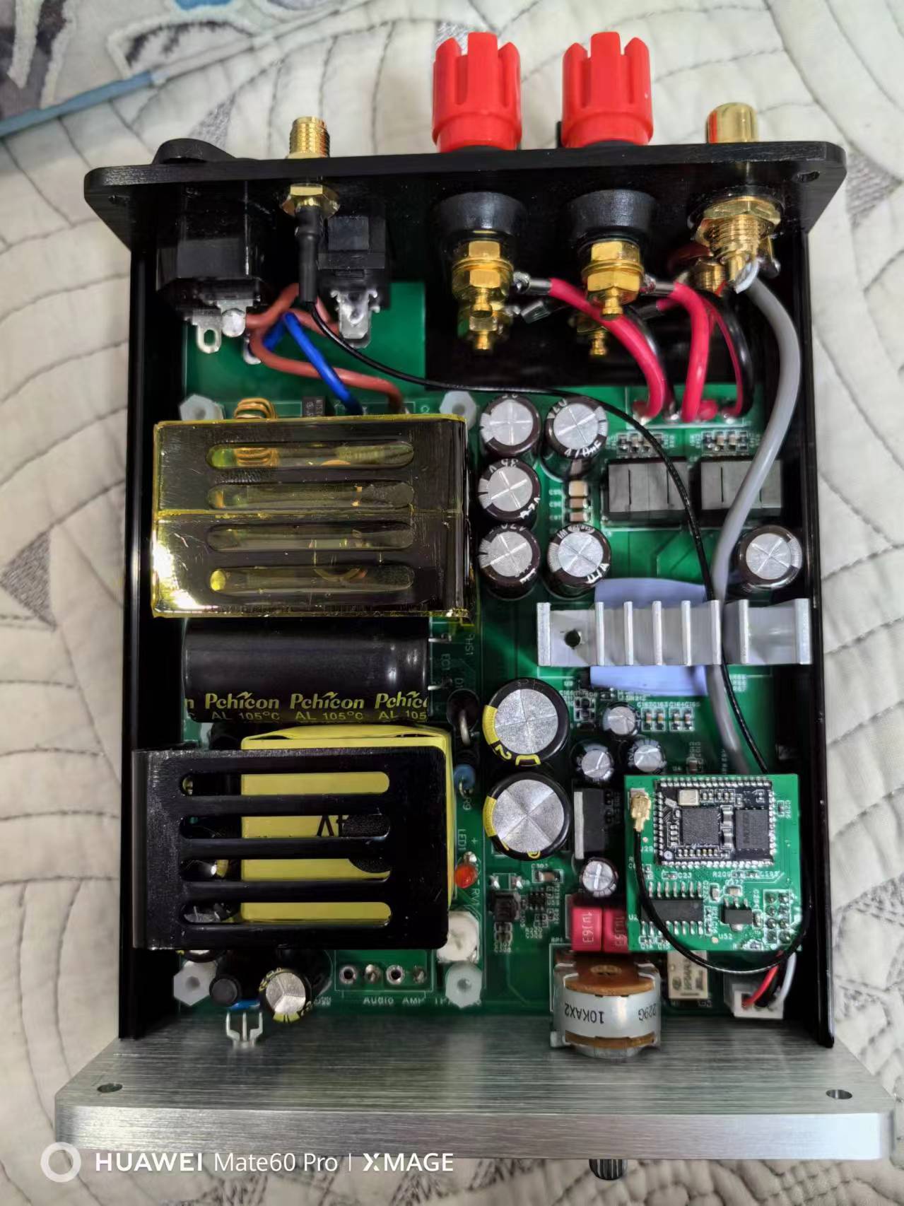
The design goal is to integrate Bluetooth and aux inputs, with a built-in switching power supply. The sound quality just needs to be acceptable. Power Supply: I chose a 24V 5A LCC power module from Taobao. Circuit Design:
1. The amplifier chip I chose is a TPA3126D2. Without considering THD+N, it can achieve 2x50W output power with a 4Ω load. In actual use, when paired with bookshelf speakers with good sensitivity, the output power is generally very low, rarely exceeding 10Wx2. 2. The actual op-amp I soldered is a TL072. 3. The Bluetooth module I chose is a Qualcomm QCC3034 module (I2S output, mainly because I happened to have one on hand) . 4. Bluetooth DAC module: ES9023. This is just a basic amplifier for basic sound output; I don't have particularly high requirements for sound quality. Connecting the Bluetooth to the relay switches to Bluetooth input. To avoid problems, a transformer coupling was added for the Bluetooth audio. The amplifier output low-pass filter uses a high-power common-mode inductor specifically designed for digital amplifier audio. The actual sound quality is acceptable, haha. Regarding pop-up noise reduction, TI has an official document explaining how their Class D amplifier chips eliminate pop-up noise. You can check it out and study it. The root cause of pop-up noise is input signal mismatch, such as impedance mismatch between the positive and negative terminals. The main solutions to reduce pop-up noise are: 1. Reduce input capacitance; 2. Reduce gain; 3. Control output on/off; 4. Control chip power-on/off timing. This design solution is: 1. Uses a 3.3uf ceramic capacitor for input coupling ; 2. Uses a reset chip for mute control during power-on and power-off. Power-on delay enables, and power-off instantaneously disables. Component Purchase Links: 1. Heatsink: https://item.taobao.com/item.htm?id=749527199086 2. Case: https://item.taobao.com/item.htm?id=543299792449 3. Power Supply Module: https://detail.tmall.com/item.htm?id=593446180966 4. Bluetooth Module: https://item.taobao.com/item.htm?id=614494660653
The CH340 is used to convert the USB signal into a TTL signal, and then the MAX485 chip is used to convert it into a differential signal.
Function: Used for host computer monitoring and debugging of industrial control equipment and instruments based on the RS485 Modbus protocol. Principle: The CH340 chip converts USB signals to TTL signals, and then the MAX485 chip converts them to differential signals. Features: Low cost. Suitable for various computer-based serial port assistants. ESD protection. Overcurrent protection. Automatic transceiver switching. Includes a 120R terminating resistor switch. Includes communication indicator lights.
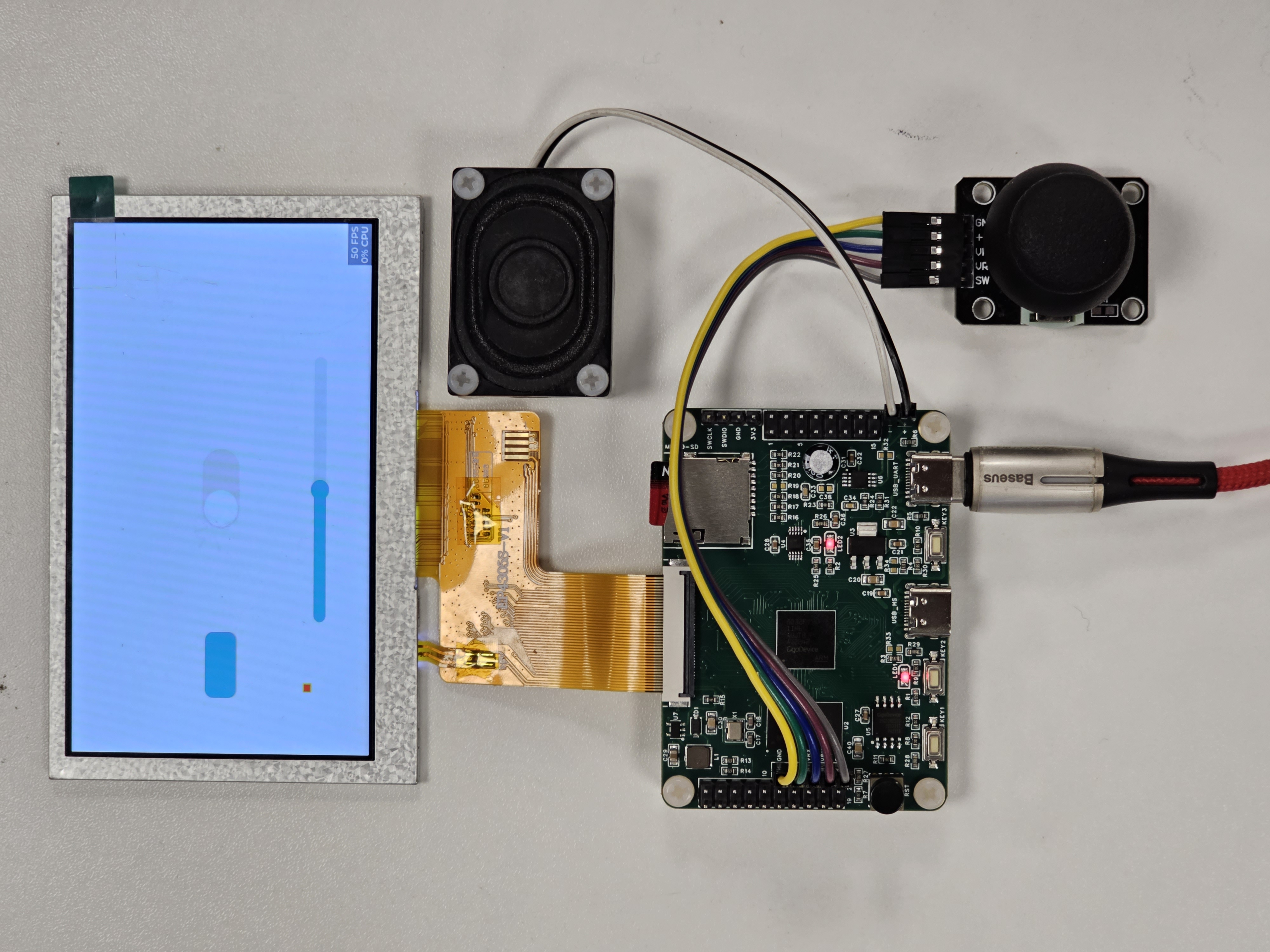
The GD32F470IIH6 development board features onboard 32-bit SDRAM, an RGB 40-pin connector, a Micro-SD card slot, and an audio amplifier.
The performance bottleneck of high-end MCUs, as designed for high-end applications, actually lies in storage. Using 32-bit SDRAM to increase data bandwidth is the right approach
. Even with high-load LVGL, a high-frequency Cortex-M4 with 32-bit SDRAM can run quite well. However, many commercially available boards, even those with M7 processors, use 16-bit SDRAM, which is incomprehensible.
The purpose of this board is to use a 240MHz Cortex-M4 + 32-bit SDRAM + RGB 40-pin to power an 800*480 screen running LVGL.
SPI Flash, Micro-SD card, and audio amplifier, which may be needed for the GUI, are also onboard for easy use.
This development board is compatible with all BGA176 GD32F4 chipsets
, including GD32F450IGH6/GD32F450IIH6/GD32F450IKH6/GD32F470IGH6/GD32F470IIH6/GD32F470IKH6.
GitHub The example programs provided in the GitHub repository
(https://github.com/legacyvv/GD32F470IIH6 ) have all passed
physical testing . The LVGL example program, using a GD32F470IIH6 and IS42S32800G-6BLI, successfully completed a 3-day continuous test of `lv_demo_stress()` with no component burn-out or screen flickering. Software Notes: There is a pin conflict between the SDRAM's NBL and RGB888 pins, so the MCU's NBL0-3 is not connected to the SDRAM. On the SDRAM side, the corresponding DQM0-3 is directly shorted to GND. When operating SDRAM data, pay attention to 32-bit alignment, lamination, and impedance . Board thickness is 1.6mm. JLCPCB 3313 (the free one) Main Components : MCU: GD32F470IIH6; SDRAM: IS42S32800J-7BL; SPI FLASH: GD25Q128ESIGR; USB to Serial: CH340E LCD backlight driver: SGM3766; Audio amplifier: BL6306MM. Regarding component sourcing, please verify authenticity yourself. It's recommended to buy the MCU yourself; LCSC's GD32F4 series is incomplete. LCSC has the IS42S32800J-7BL SDRAM, but there are many low-priced IS42S32800G-6BLI on Taobao, which you can also buy yourself. Note that the 800G is an older version with higher power consumption than the 800J; please refer to the datasheet for specific data. LCSC does not have the SGM3766; buy it yourself.
PDF_GD32F470IIH6 development board.zip
Altium_GD32F470IIH6 development board.zip
PADS_GD32F470IIH6 development board.zip
BOM_GD32F470IIH6 Development Board.xlsx
94965
Arduino-based 4008/4010 motor FOC driver
The ATmega328P is the MCU, the DRV8313 is the motor driver, the AS5600 is the encoder (I2C mode), the TJA1050T is the CAN communication chip, and the INA199 is used to read the current.
Three-phase interface:
PD3->A phase
PD5->B phase
PD6->C phase
EN pin:
PD4
I2C:
PC5->SCL
PC4->SDA
INA199:
PC1->A phase current
PC2->B phase current
PC3->C phase current
DIP switch:
PB1->SET1
PB2->SET2
CAN transceiver interface:
PD7->TX_CAN
PB0->RX_CAN
//CAN chip & AS5600 not yet verified
cfcfae4b981fe8f37adc50d49e282e5b.mp4
PDF_Arduino-based 4008-4010 motor FOC driver.zip
Altium_Arduino-based 4008_4010 motor FOC driver.zip
PADS_Arduino-based 4008_4010 Motor FOC Driver.zip
BOM_Arduino-based 4008_4010 Motor FOC Driver.xlsx
94967
USB 2.0 expansion dock based on SL2.1A
This is a USB 2.0 docking station made with the SL2.1A chip and uses a current limiting circuit to prevent it from burning out.
Main control chip circuit:
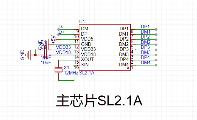
This chip can be purchased from LCSC Mall or Taobao
. Current limiting circuit:

A current limiting circuit is used to avoid damage to the computer caused by short circuits.
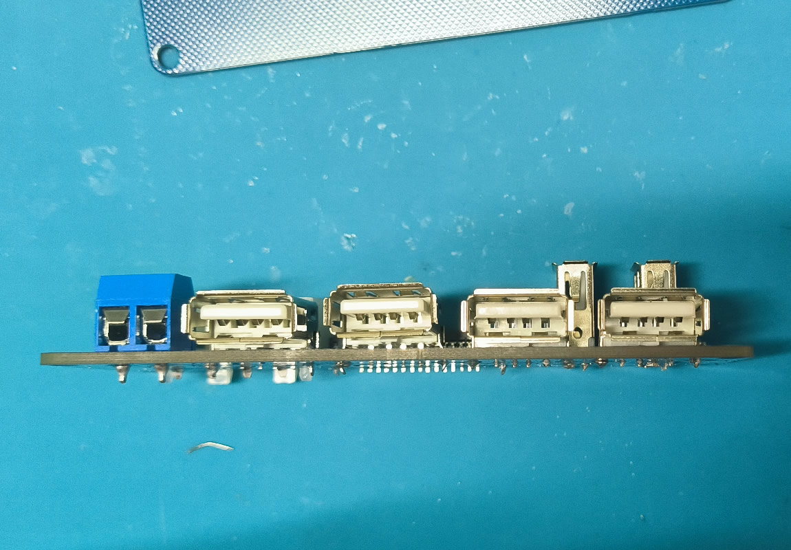
Actual product image:
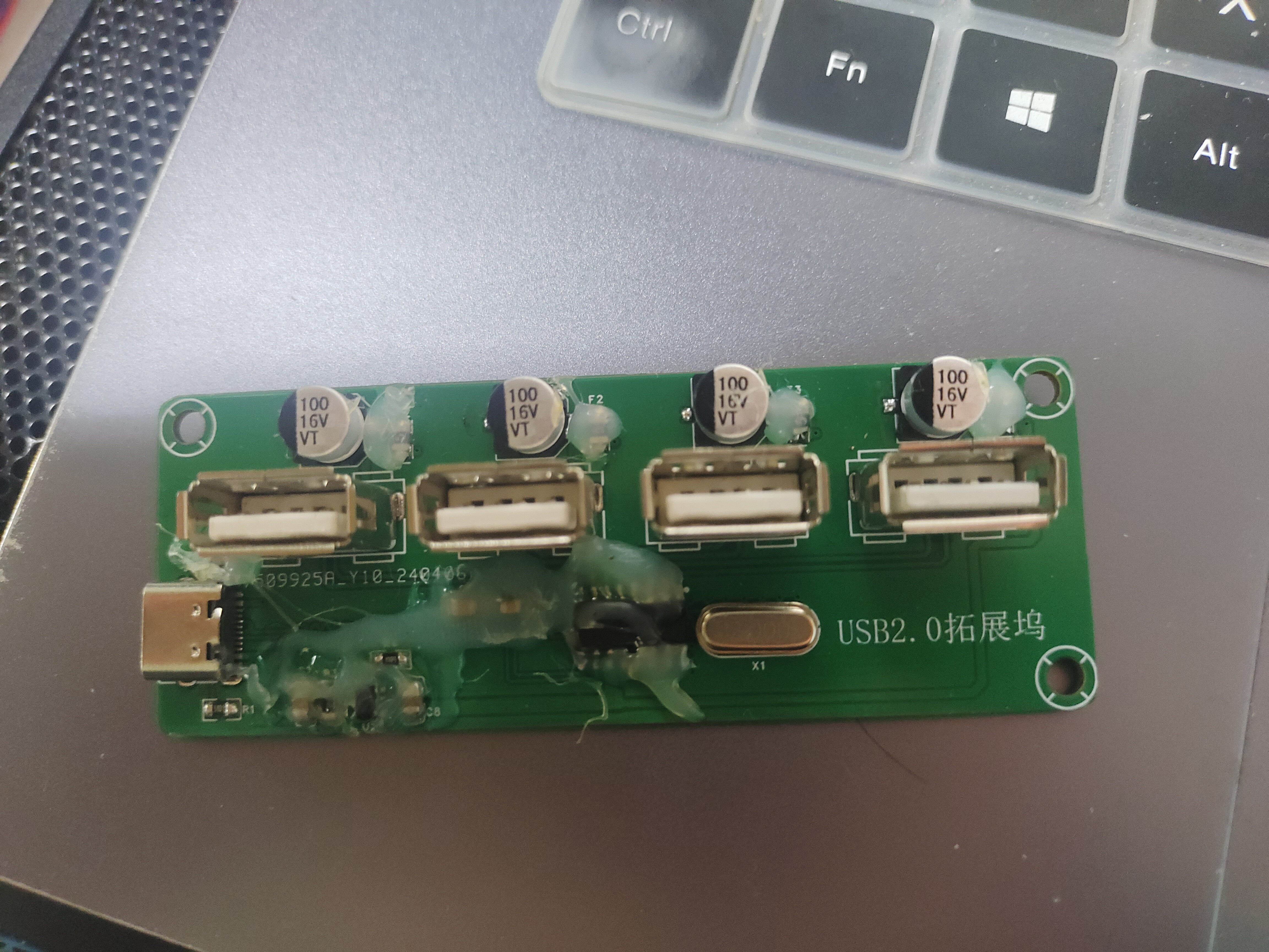
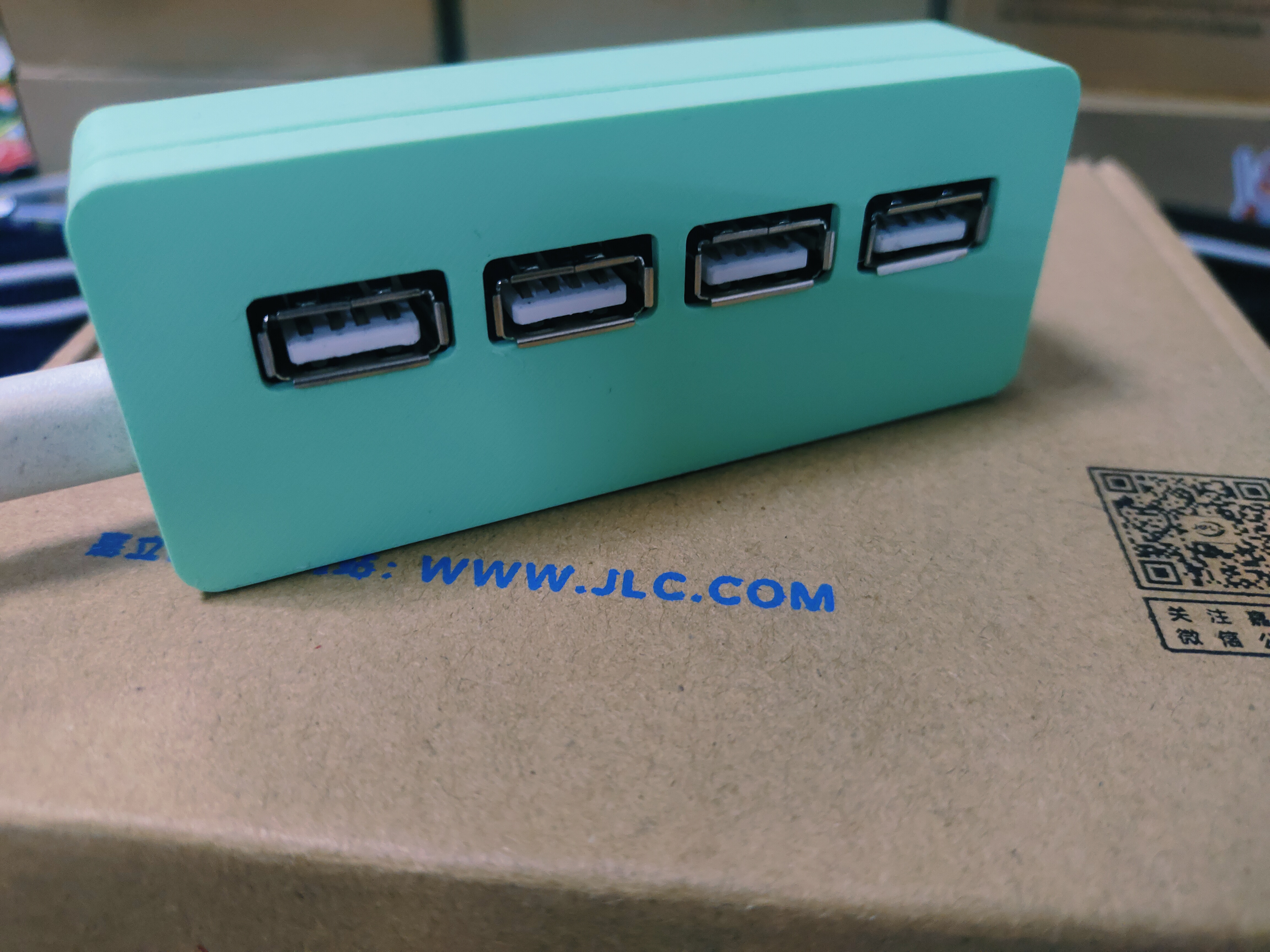
Tested and working; those interested can place an order. By the way, it's best to use the Type-C version; the Type-A version seems to have some minor issues. I recommend ordering the Type-C version docking station. The shell file is provided below.
video_20240428_110618_edit.mp4
3DShell_3DShell_PCB1_B.step
3DShell_3DShell_PCB1_T.step
PDF_USB2.0 Expansion Dock Based on SL2.1A.zip
Altium_USB2.0 Dock Based on SL2.1A.zip
PADS_USB2.0 Dock Based on SL2.1A.zip
BOM_USB2.0 Dock Based on SL2.1A.xlsx
94968
ESP_UFB project
ESP series universal flashing board. DCDC version and LDO version.
Version 0 Update
Version Name: ESP Series Universal Flashing Board V1.1, V1.2
Update Time: 2023/11/16
I. Project Introduction
Project Introduction Video
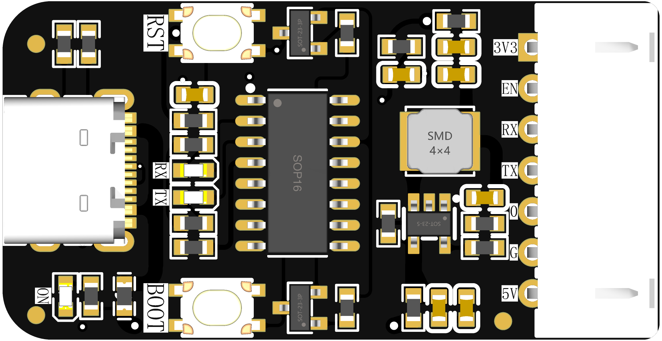
The ESP series universal flashing board can flash ESP32-Cx, ESP32, ESP32-Sx and other ESP series chips; this project has DCDC and LDO versions, which you can choose according to your needs. Module separation is a cost-reduction and efficiency-enhancing approach that is widely used.
II. Effect Diagrams

III. Functional Modules
1. USB Module The

USB interface is the more common Type-C interface, which can be plugged in either way.
2. Automatic Flashing Module
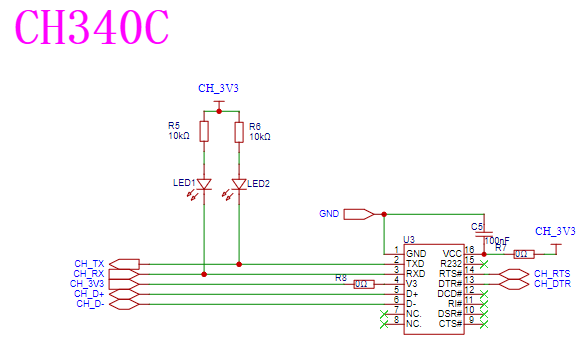
The flashing chip is the common and low-cost CH340C. RX and TX are each connected to an indicator light to indicate the flashing status. A 0 resistor is added to the power supply for easy debugging and maintenance.
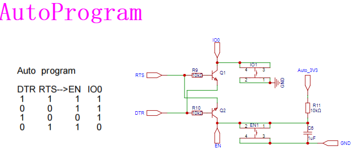
The timing of automatic flashing is shown in the figure, which can be referred to the Espressif manual for details. Two buttons are reserved for manual flashing compatibility.
3.1 LDO Converter Module

The step-down module is the common and low-cost AMS1117, which can output a current of up to 1A. The rest are standard designs and require no further explanation.
3.2 The DC-DC converter/

step-down module uses the ETA3409S2F, which can output up to 3A. The choice of resistors R6 and R7 can be based on your needs; here, 100kΩ and 22kΩ are chosen. The calculation formula can be found in the chip's datasheet. Other resistors and capacitors are standard.
4. Flashing Interface :
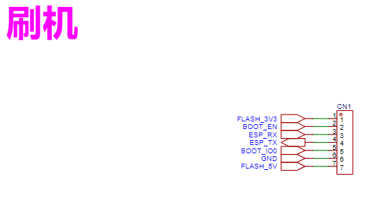
This is a 7-pin connector. Pay special attention to the pinout; carefully check this pinout on your custom-designed board!
IV. Notes:
This project will be continuously improved and
updated. Updates will be made on the 15th or the last day of each month.
Access methods:
UP: open01_T_Jupiter; duduvue;
QQ: 826793815.
Subsequent open-source projects and updates will be released on Bilibili, LCSC Open Source Platform, Github, and Gitee. Please follow for real-time updates!
PDF_ESP_UFB project.zip
Altium_ESP_UFB project.zip
PADS_ESP_UFB project.zip
BOM_ESP_UFB project.xlsx
94969
ST-LINK V2 20Pin to 4Pin Adapter Board_v1.2
This is a 20-pin to 4-pin adapter board compatible with ST's official ST-LINK V2 and common C8T6 minimum core boards, and also supports Type-C conversion. For personal use.
This is a 20-pin to 4-pin adapter board compatible with ST's official ST-LINK V2 and common C8T6 minimum core boards, and also supports Type-C conversion. For personal use.
A TVCC and 3.3V interface are added to the back; shorting these is recommended. When not connected, an additional 3.3V power supply is required for the microcontroller; otherwise, there is a risk of burning out the link.
1.jpg
2.jpg
1.mp4
PDF_ST-LINK V2 20Pin to 4Pin Adapter Board_v1.2.zip
Altium_ST-LINK V2 20Pin to 4Pin Adapter Board_v1.2.zip
PADS_ST-LINK V2 20Pin to 4Pin Adapter Board_v1.2.zip
BOM_ST-LINK V2 20Pin to 4Pin Adapter Board_v1.2.xlsx
94970
ESP32-C3 bare die development board - minor modifications - verification version
The ESP32-C3 bare die development board, based on the iVanli version, adds an onboard antenna; the dual USB-C interfaces have been changed to a direct-plug type; the USB-to-serial chip CH340X + USB CDC has been tested and verified.
Using a spare ESP32-C3FH4 die, and referencing the open-source version at https://oshwhub.com/ivanli/esp32-c3-chip-mini-board, an onboard antenna was added. Because it's for testing and frequent plugging and unplugging is inevitable, the surface-mount Type-C connector was replaced with a through-hole Type-C connector, presumably for better stability. The schematic remains largely unchanged, so only the modified PCB layout is provided for those who need it. Please refer to the original BOM for the BOM as well. Only basic functions were tested after board fabrication. Feedback and corrections are welcome; thank you in advance!
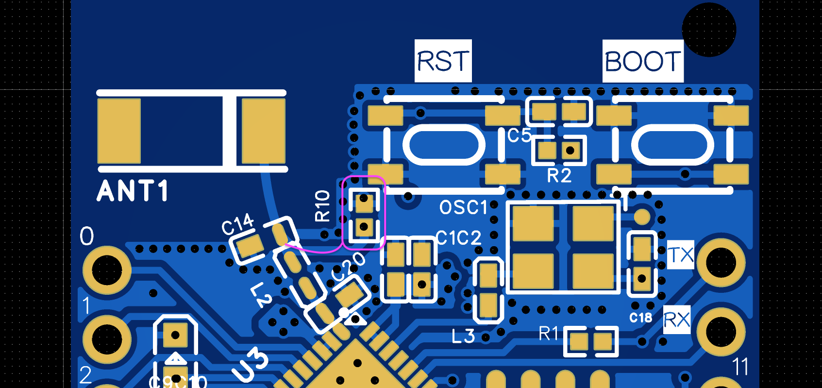
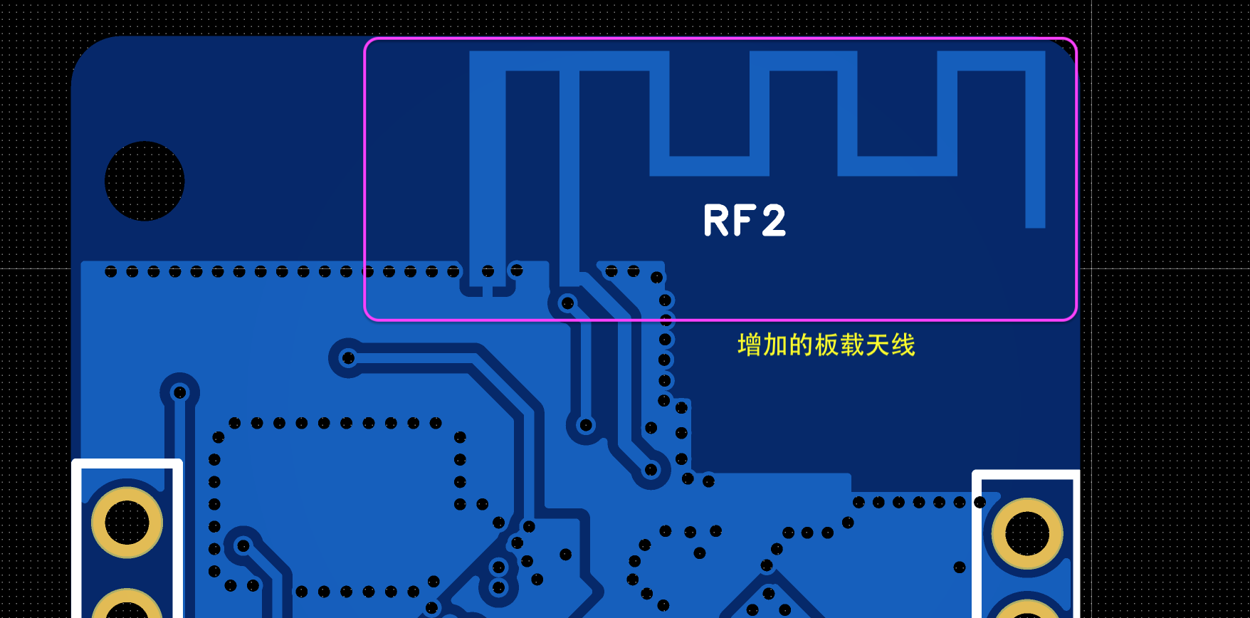
1. The added onboard antenna is achieved by adding a 0-ohm resistor to the right side of C14; if you need to use the onboard antenna, simply solder an R10 0-ohm resistor.
2. To reduce signal interference, the onboard antenna is placed on the back. To ensure good signal performance, a board thickness of 1.6mm is recommended.
The measured wireless signal is within an acceptable range. However, due to not having a CrossAir CA-C03 surface-mount wireless connector on hand, I was unable to conduct actual testing and comparison. Please provide feedback and supplementary information if you have the necessary equipment.
3. The verified version does not have C14, C20, and L2 inductors (0402 5.6pF).
4. The active crystal oscillator was purchased on Taobao, but customer service failed to provide valuable information (the load capacitance is estimated to be 20pF, 3.3V). The link below is for reference if you need to purchase one.

5. I only had an AMS1117-3.3 on hand, not the CJA1117B-3.3 listed in the BOM.
6. I heated the soldering iron plate and then did some minor manual adjustments.
Additional notes:
a) When debugging the software and flashing firmware using a USB-to-serial adapter, please ensure you are in download mode first:
(https://docs.espressif.com/projects/esp-techpedia/zh_CN/latest/esp-friends/get-started/try-firmware/try-firmware-hardware/esp32c3.html)

That is, set GPIO8 to high level and GPIO9 to low level.

b) To test the CH340X functionality, you can use the official Qinheng testing tool (RX and TX need to be shorted during testing).
Download links for the testing tool:
Windows version serial port debugging software: https://www.wch.cn/downloads/COMTransmit_ZIP.html
Mac version: Search for "wchserialport" directly in the App Store.

c) For those interested in Tasmota, you can install it via the web:
https://tasmota.github.io/install/
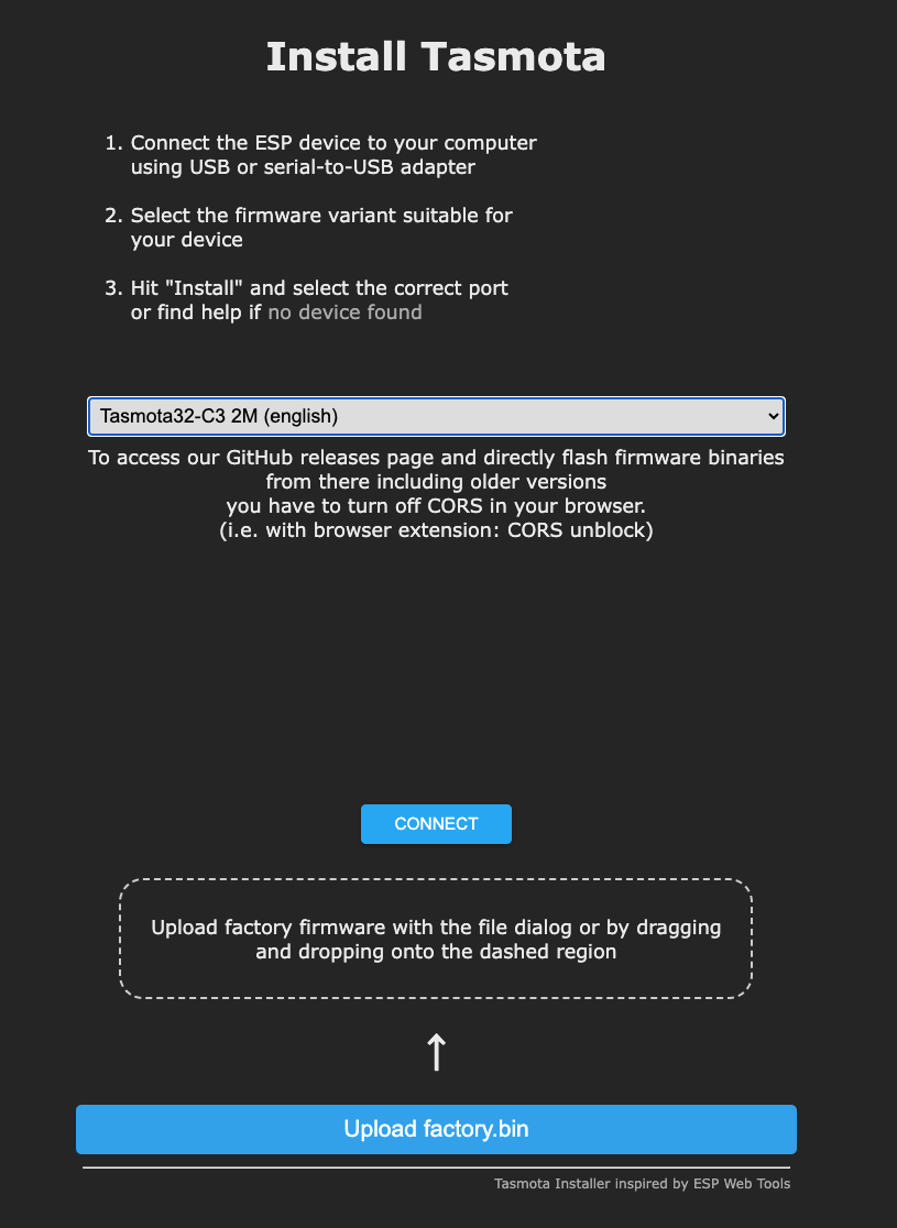
(Offline version is attached for reference).
Other versions can be found at the following download links:
https://ota.tasmota.com/tasmota32/release/ d) Download guide
for the flashing tool and AT firmware (see attachment) provided by Espressif : https://docs.espressif.com/projects/esp-at/zh_CN/latest/esp32c3/Get_Started/Downloading_guide.html AT firmware for Espressif's ESP32-C3 series modules: https://docs.espressif.com/projects/esp-at/zh_CN/latest/esp32c3/AT_Binary_Lists/esp_at_binaries.html (Official recommended version: https://dl.espressif.com/esp-at/firmwares/esp32c3/ESP32-C3-MINI-1-AT-V3.2.0.0.zip)
[ESP32C3-AT][v3.2.0.0] User Guide.pdf
COMTransmit.ZIP
ESP32-C3-MINI-1-AT-V3.2.0.0.zip
flash_download_tool_3.9.2.zip
tasmota32c3.factory.bin
PDF_ESP32-C3 bare die development board-minor modification-verification version.zip
Altium_ESP32-C3 bare die development board - minor modifications - verification version.zip
PADS_ESP32-C3 bare die development board - slightly modified - verification version.zip
BOM_ESP32-C3 bare die development board-minor modification-verification version.xlsx
94972
Pico_DM_FPC032MRA003 Raspberry Pi TFT Expansion Board
It is a low-cost display expansion board based on the Raspberry Pi Pico core board, with a resolution of 480x320, and is designed for learning, evaluating, and developing LVGL or other GUI applications.
The Pico_DM_FPC032MRA003 is a low-cost display expansion board based on the Raspberry Pi Pico core board. It has a resolution of 480x320 and is specifically designed for learning, evaluating, and developing LVGL or other GUI applications.
System Specifications: Screen Resolution: 480x320; Screen Driver IC: R61581; Screen Interface Type: I80 16-bit; Touch Driver IC: TSC2007.
Documentation Link: http://embeddedboys.com/Pico_DM_FPC032MRA003/
Code Repository: https://gitee.com/embeddedboys/pico_dm_fpc032mra003_freertos
Official Purchase Link: Bilibili Workshop (bilibili.com)
. Supports development using pico-sdk or MicroPython.
This project is released under the MIT License and features a completely open-source software and hardware design.
PDF_Pico_DM_FPC032MRA003 Raspberry Pi TFT Expansion Board.zip
Altium_Pico_DM_FPC032MRA003 Raspberry Pi TFT Expansion Board.zip
PADS_Pico_DM_FPC032MRA003 Raspberry Pi TFT Expansion Board.zip
BOM_Pico_DM_FPC032MRA003 Raspberry Pi TFT Expansion Board.xlsx
94973
SATA power to USB board
Desktop SATA power connector to USB adapter for powering USB devices.
This desktop SATA power adapter to USB port is used to power USB devices.
The power input can be either a 4-pin (large 4-pin) or a 15-pin (SATA) connector, depending on your desktop's power supply.
Each USB port has a pre-installed resettable fuse; you can short it if you don't want to use it.
In addition to the 5V USB ports, a 12V output is also provided.

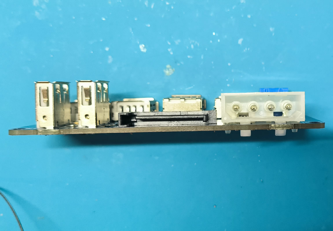

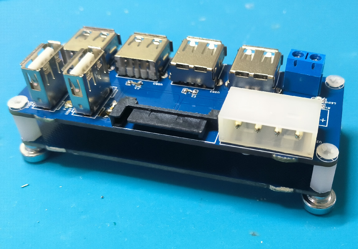
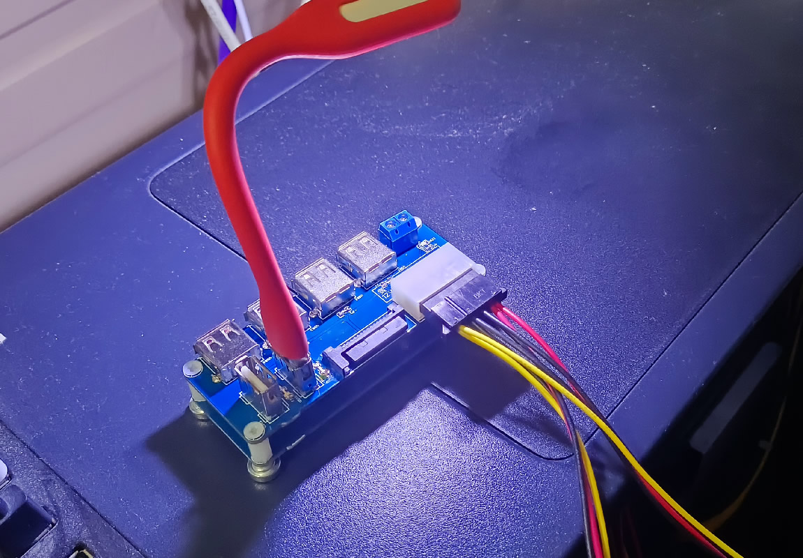
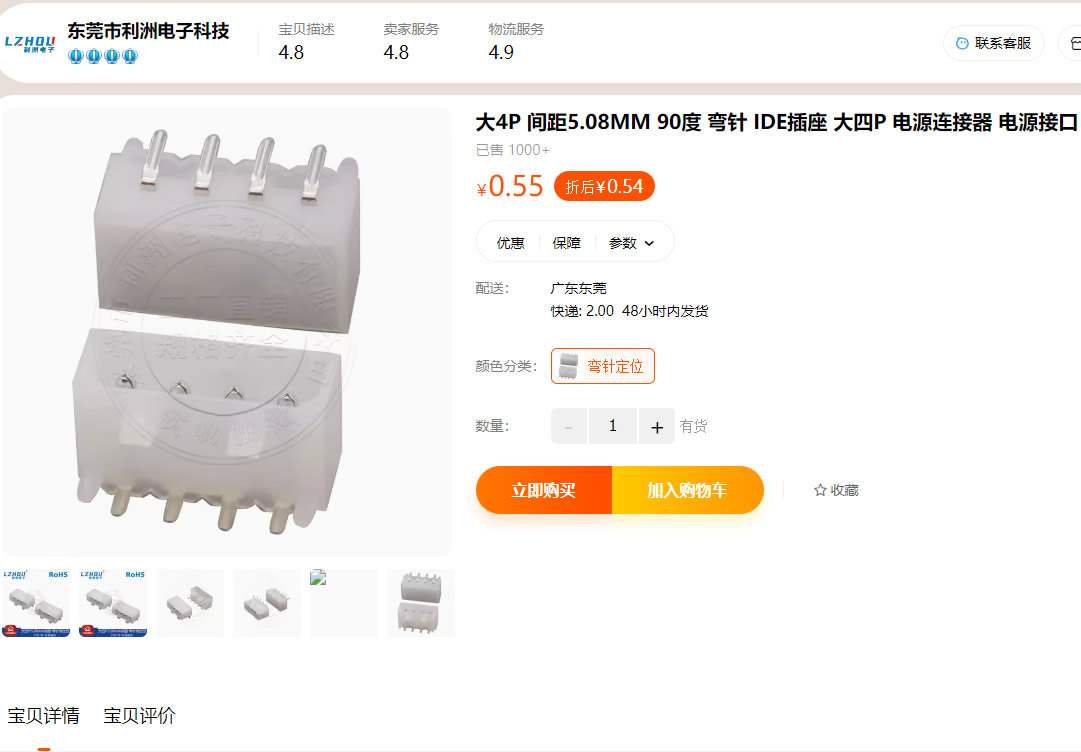
(See attached purchase pages for SATA 15-pin and 4-pin connectors.)

PDF_SATA Power to USB Converter Board.zip
Altium_SATA power to USB board.zip
PADS_SATA Power to USB Board.zip
BOM_SATA Power to USB Converter Board.xlsx
94974
electronic


 京公网安备 11010802033920号

 2SK1429-RB


