0. PCBA Version
The current description of the compatible version is V01-20231214
. 1. Scope of application:
This project is a TYPE-C debugging adapter board, which is suitable for projects with TYPE-C connectors for debugging. For example, for the 8155 host, S61 FCM project
2. Version Description:
This PCBA has two versions, one for the 8155 host and the other for the S61 FCM project (the pin definitions of the TYPE-C male connectors for the two projects are different); they are not interchangeable. Please pay attention to whether they are applicable to the current project before use.
The method of differentiation is shown in the figure below:
PN1: 0402 package resistors in columns 1 and 3 on the right side of the TYPE-C male connector in the S61 FCM version; the TYPE-
C male connector in the S61 FCM version does not support reversible insertion. PN2: 0402 package resistors in columns 2 and 4 on the right side of the TYPE-C male connector in the 8155 version; the TYPE-C male connector in the 8155 version supports reversible insertion.

3. Function Description:

3.1 USB TYPE-C Male Connector: Used to connect the TYPE-C female connector on the DUT PCBA.
8155 Project Function: Used to connect the TYPE-C female connector on the DUT PCBA, supports reversible insertion.
S61 FCM Project Function: Used to connect the TYPE-C female connector on the DUT PCBA, does not support reversible insertion.
3.2 SW1 Switch:
8155 Project Function:
Switch to upper position -> NA
switch to middle position -> Normal operation
switch to lower position -> USB programming mode.
S61 FCM Project Function (SoC_EMU0):
Switch to upper position -> NA
switch to middle position -> Normal operation
switch to lower position -> Enter JTAG boundary scan mode.
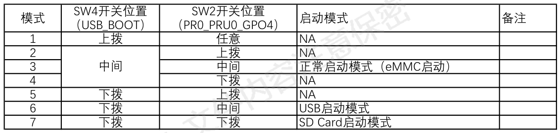
3.3 SW2 Switch:
8155 Project Function: NA.
S61 FCM Project Function (PR0_PRU0_GPO4):
3.4 SW3 Switch:
8155 Project Function: NA.
S61 FCM Project Function (WatchDog_Shield_EN):
Switch to upper position -> Shield WTD watchdog function.
Switch to middle position -> Normal operation
switch to lower position -> NA.
3.5 SW4 Switch:
8155 Project Function: NA.
S61 FCM Project Function (USB_BOOT):
3.6 DC-3_1.27mm_20P Connector:
Connects to J-LINK via a gray ribbon cable, using the JTAG/SWD interface to program the MCU in the DUT.
Gray ribbon cable link: https://item.taobao.com/item.htm?spm=a1z09.2.0.0.17182e8d8Ox6LK&id=743314902167&_u=l1f60ejq4e4f
Gray ribbon cable specifications: 1.27 to 2.54 20P, 200mm
Note: Both ends of the gray ribbon cable have a foolproof design, as shown in the picture below. Pay attention to the orientation when installing the gray ribbon cable, otherwise the MCU software inside the DUT cannot be programmed.
(Image to be added)
3.7 USB TYPE-C Female Connector 1:
8155 Project Function: NA
3.8 USB TYPE-A Female Connector:
8155 Project Function: NA
3.9 USB TYPE-C female connector 2:
This port is the USB interface for the onboard USB to UART module. If the board has an onboard CH343P module, it can be connected to a computer via a USB TYPE-A to TYPE-C data cable (Android TYPE-C data cable) to use a serial communication host computer to communicate with the MCU/SOC inside the DUT.
3.10 UART Voltage Selection Switch:
Level selection for the DUT's onboard MCU/SOC UART port:
Switch in the upper position -> 3.3V;
Switch in the middle position -> 1.8V;
Switch in the lower position -> 5.0V.
UART level selection reference:
8155 Project:
MCU: 3.3V;
SOC: 1.8V;
S61 FCM Project:
MCU: 3.3V
; SOC: 3.3V.
Note: Please select this switch correctly. Incorrect selection will prevent the PC host computer from communicating normally with the MCU/SOC inside the DUT via UART.
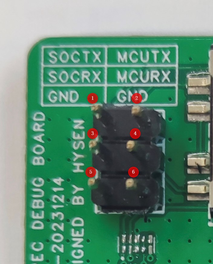
3.11 UART Pin Headers:
Pin 1: DUT SOCTX, needs to be connected to the RX pin of the serial port board . Pin
2: DUT MCUTX, needs to be connected to the RX pin of the serial port board.
Pin 3: DUT... SOCRX, needs to be connected to the TX pin of the serial port board
. Pin 4: DUT MCURX, needs to be connected to the TX pin of the serial
port board. Pin 5: GND, one of pins 5/6 must be connected to the GND of the external USB to UART serial port board; otherwise, the PC host computer cannot communicate normally with the MCU/SOC inside the DUT via UART .
Pin 6: GND, one of pins 5/6 must be connected to the GND of the external USB to UART serial port board; otherwise, the PC host computer cannot communicate normally with the MCU/SOC inside the DUT via UART
. Note: If connecting to the external USB to UART serial port board via UART header pins, the [3.12 UART Channel Selection Switch] must be set to the middle position; otherwise, the PC host computer cannot communicate normally with the MCU/SOC inside the DUT via UART.
3.12 UART Channel Selection Switch:
[3.9 USB...] 【TYPE-C Female Connector 2】When using the onboard CH343P module, this switch is required to select the communication target. With the switch
in the upper position -> SOC, communication with the SOC via the UART interface is selected.
With the switch in the middle position -> OPEN, in the open circuit state, communication with the PC via the external serial port board is achieved through 【3.11 UART header】. With the switch
in the lower position -> MCU, communication with the MCU via the UART interface is selected.
4. Instructions for Use:
4.1 Using this TYPE-C debugging adapter board to program the 8155 MCU
4.1.1 Preparation
①DUT-8155 host
② Host power supply harness
③ Adjustable power supply
④ TYPE-C debug adapter board
⑤ Gray ribbon cable (1.27 to 2.54 20P)
⑥ J-LINK debugger
⑦ J-LINK USB square port harness
⑧ PC
4.1.2 Environment Setup
4.1.3 Programming steps
refer to the corresponding ESW output guide document
(to be updated
) 4.2 Using this TYPE-C debug adapter board to program the 8155 SOC (
to be updated
) 4.3 Using this TYPE-C debug adapter board to program the S61 FCM MCU
(to be updated
) 4.4 Using this TYPE-C debug adapter board to program the S61 FCM SOC
(to be updated
) 4.5 Using this TYPE-C debug adapter board to perform UART communication with the DUT's internal MCU (using the onboard CH343P module - USB to UART) (
to be updated )
4.6 Using this TYPE-C debug adapter board to perform UART communication with the DUT's internal SOC (using the onboard CH343P module - USB to UART)
(to be updated
) 4.7 Use this Type-C debug adapter board to establish UART communication with the DUT's internal MCU (using an external USB to UART serial port board).
(To be updated
4.8) Use this Type-C debug adapter board to establish UART communication with the DUT's internal SOC (using an external USB to UART serial port board).
(To be updated )


 京公网安备 11010802033920号

 301330M100EG2


