The entire design can be completed with relatively simple resistors, capacitors, and inductors.
PDF_Portable Power Bank Based on IP5506.zip
Altium_IP5506-based portable power bank.zip
PADS_IP5506-based Portable Power Bank.zip
BOM_Portable Power Bank Based on IP5506.xlsx
97373
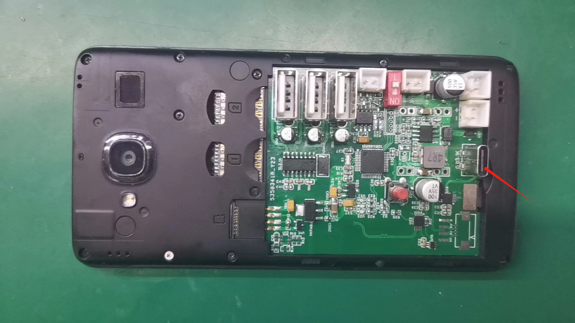
Redmi power supply board has onboard U2C
Powered by Redmi 2, automatically powers on upon power-up, and features an OTG 3-in-1 board. Provides wide voltage input support from 10~28V. Includes USB 2.0 docking station functionality and CAN bus, allowing for independent U2C firmware updates.
Overview: This document
adds CAN bus support to the "Redmi 2 Direct Power OTG Automatic Power-On Three-in-One Board," and supports independent USB updates for CAN firmware and KLIPPER. It uses a reversible Type-C connector for update selection, automatically entering OTG mode without requiring a DIP switch.
Update Process:
Klipper Update

1. Put the phone into FASTBOOT mode, connect the Type-C cable, and use the Klipper firmware flashing software to check the phone's connection status. If the phone is not recognized, rotate the Type-C connector and continue connecting. The phone will be correctly recognized, and then Klipper can be flashed.
CAN Update

1. Power on the power board and connect the Type-C cable
. 2. Press and hold the red button for one second, then release.
3. Go to the upgrade website Updater - CANable
. 4. Select the version and firmware, and click Firmware Upgrade.
5. If the device is not recognized, reverse the Type-C connector and reinsert it, repeating steps 2-4.
Notes:
1. In the schematic diagram, R15, C15, R14, R16, R13, and U12 represent an alternative chip scheme. Choose one of them, along with U11.
2. Select the appropriate button height based on the case height.
3. It is recommended that the following ports be exposed outside the case: USB port, Type-C port, buttons, CAN bus port, and power port.
4. The fan port is for heat dissipation.
5. Choose any PCB that's free; 1.6mm thick, everyone knows that!
6. Ensure the board fits snugly against the phone case during installation to prevent it from being pulled out when plugging/unplugging the Type-C port during firmware updates.
Follow-up
: 1. Please refer to the detailed Klipper configuration yourself. The matching CAN head board is currently being tested. Alternatively, you can choose a commercially available CAN tool board for connection.
2. Due to time constraints, I will not create a group to answer questions. Instead, I recommend the technical exchange group: 883298710.
Thanks to
umekoko.
PDF_Redmi Power Supply Board Onboard U2C.zip
Altium_Redmi Power Supply Board Onboard U2C.zip
PADS_Redmi Power Supply Board Onboard U2C.zip
BOM_Redmi Power Supply Board Onboard U2C.xlsx
97374
USTC Campus Card
The school badge-style student ID card incorporates campus elements, making it both attractive and practical.
PDF_USTC Campus Card.zip
Altium_USTC Campus Card.zip
PADS_USTC Campus Card.zip
BOM_USTC Campus Card.xlsx
97376
NFC electronic business card
The NFC business card designed with NXP's NT3H1101W0FHKH is a perfect match for color silkscreen printing.
This design was completed under the guidance of Bilibili influencer "China's Slash Youth";
the circuit requires very few components and is easy to draw.
PDF_NFC Electronic Business Card.zip
Altium_NFC Electronic Business Card.zip
PADS_NFC Electronic Business Card.zip
BOM_NFC Electronic Business Card.xlsx
97377
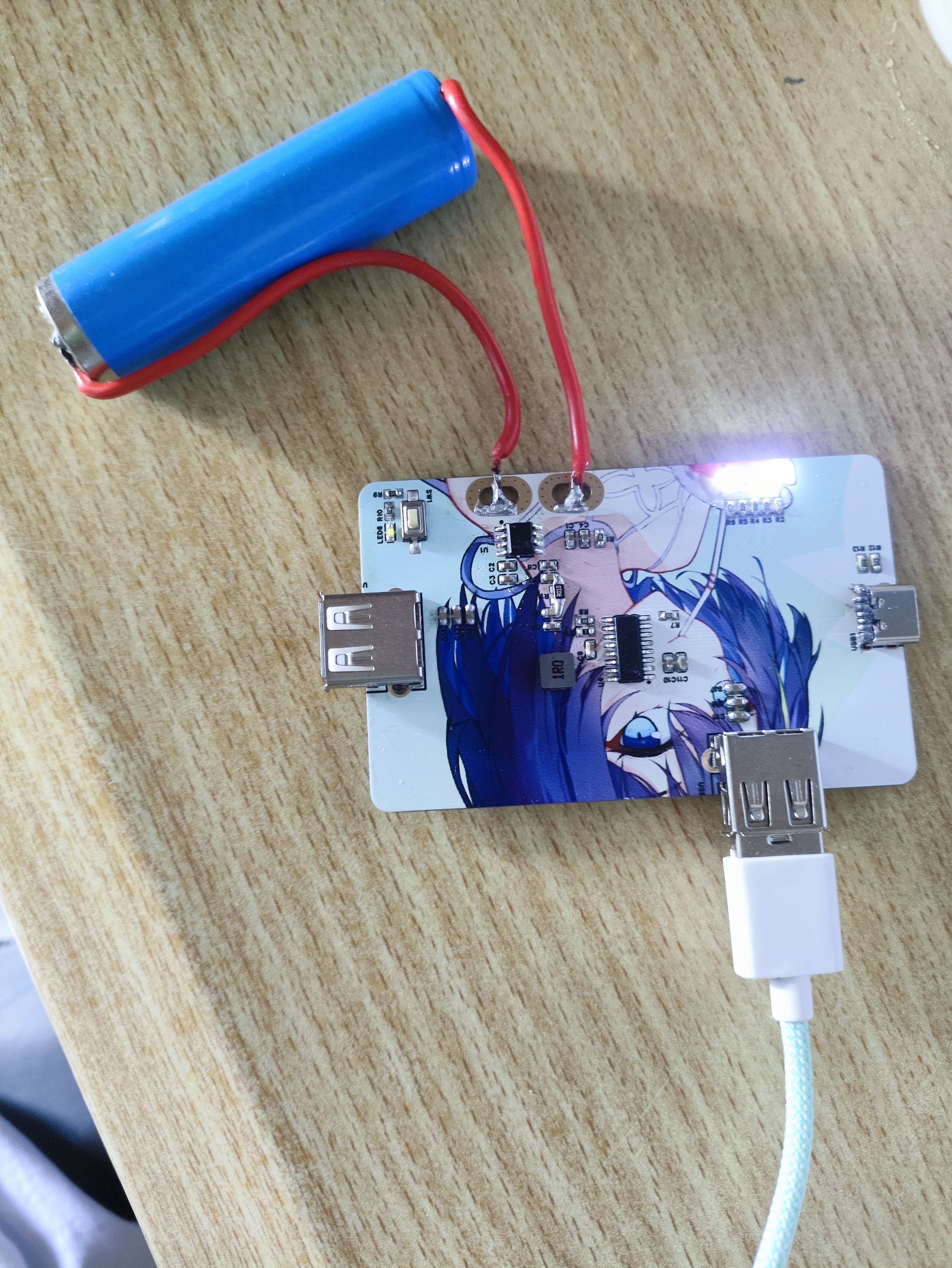
3-cell 18650 lithium battery charging board
This lithium battery boost chip, based on Injoinic's IP2326, provides fast charging of three-cell lithium batteries at approximately 15W and supports low-voltage trickle charging to activate the batteries.
The circuit is very simple and only requires resistors, capacitors, and inductors.
PDF_3-cell 18650 lithium battery charging board.zip
Altium 3-cell 18650 lithium battery charging board.zip
PADS_3-cell 18650 lithium battery charging board.zip
BOM_3-cell 18650 lithium battery charging board.xlsx
97378
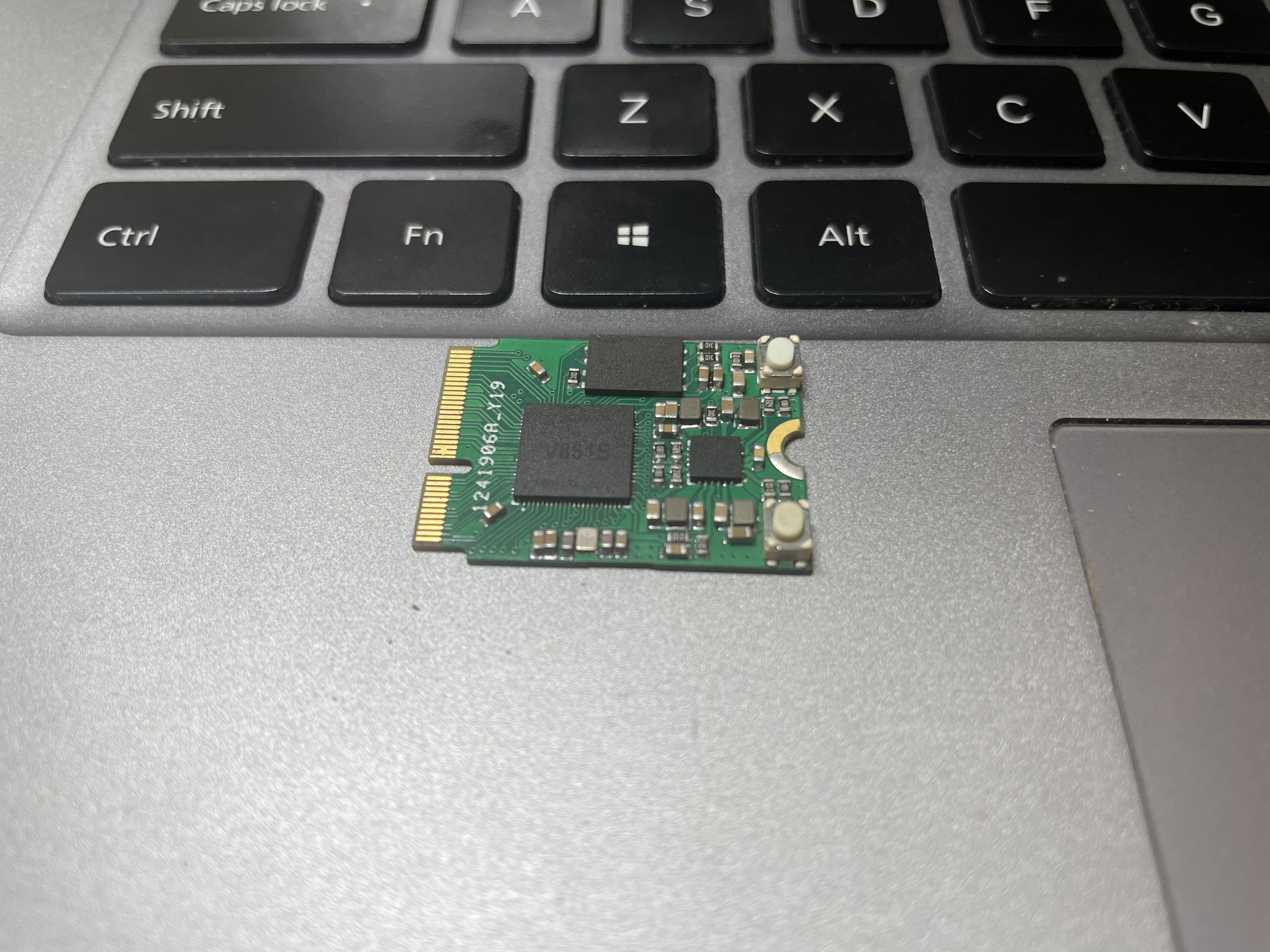
Z-Core
Based on the Allwinner V851S core board, the schematic diagram is based on @YuzukiTsuru's Yuzuki PI. Special thanks to group member @fawen for testing and support.
1. When prototyping, choose JLC7628 impedance and 0.8mm thickness (important). If you want a free sample, 1.0mm thickness is also acceptable.
2. Those with ample funds can choose immersion gold plating.
3. For those with deep pockets, JLCPCB SMT process is recommended (if you're doing immersion gold plating + SMT, send me a sample, I'd be extremely grateful :)).
4. Baseboard: V851s-ext - JLCPCB EDA open-source hardware platform (oshwhub.com)
5. Interface: NGFF M.2 E-Key
6. The two capacitors on the back of the board can be omitted; it won't affect functionality.

PDF_Z-Core.zip
Altium_Z-Core.zip
PADS_Z-Core.zip
BOM_Z-Core.xlsx
97382
AI-M61-32S Expansion Board
Anxinco AI-M61-32S-Kit Module Expansion Board
The Anxinco AI-M61-32S-Kit module expansion board includes several onboard peripherals that can be used to familiarize yourself with some of the functions of the Anxinco M61 module. These include a screen, clock, RGB LEDs, photoresistors, relays, buzzers, infrared LEDs, temperature and humidity sensors, and matrix buttons. You can also order one if you like.
PDF_AI-M61-32S Expansion Board.zip
Altium_AI-M61-32S Expansion Board.zip
PADS_AI-M61-32S Expansion Board.zip
BOM_AI-M61-32S Expansion Board.xlsx
97383
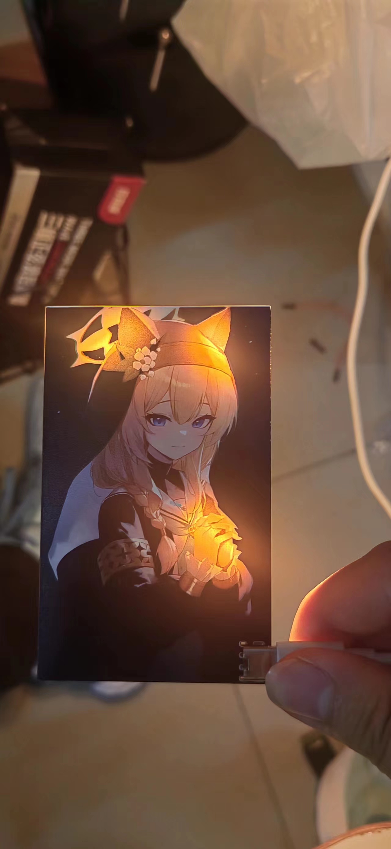
Ilomara's Colored Light Painting
I used color screen printing to create a light painting of Mary, and the effect is pretty good.
I got a free color screen printing coupon from JLCPCB. Since it was my first time designing an open-source project and I didn't have any good ideas,
I happened to see a picture with nice lighting, so I used it as my

lighting design. The circuit design is the overused TP223 touch circuit, so I won't go into detail; a quick search on Baidu yields tons of diagrams.
The design is very simple: cut out a portrait in Photoshop, place it on the top layer to block the light, and then design a few ceramic lamps for highlight areas on the bottom.
Since the highlights in the original image were already very clear, it was even simpler.
However,
because the ceramic lamps didn't provide enough diffused light, the secondary light-emitting positions weren't really visible. So
,
I quickly designed a reflective base, focusing on a simple
design. Adding a bottom cover to the printer

makes a big difference. The floodlight is reflected by the white material underneath onto the entire panel, giving the portrait a subtle glow.
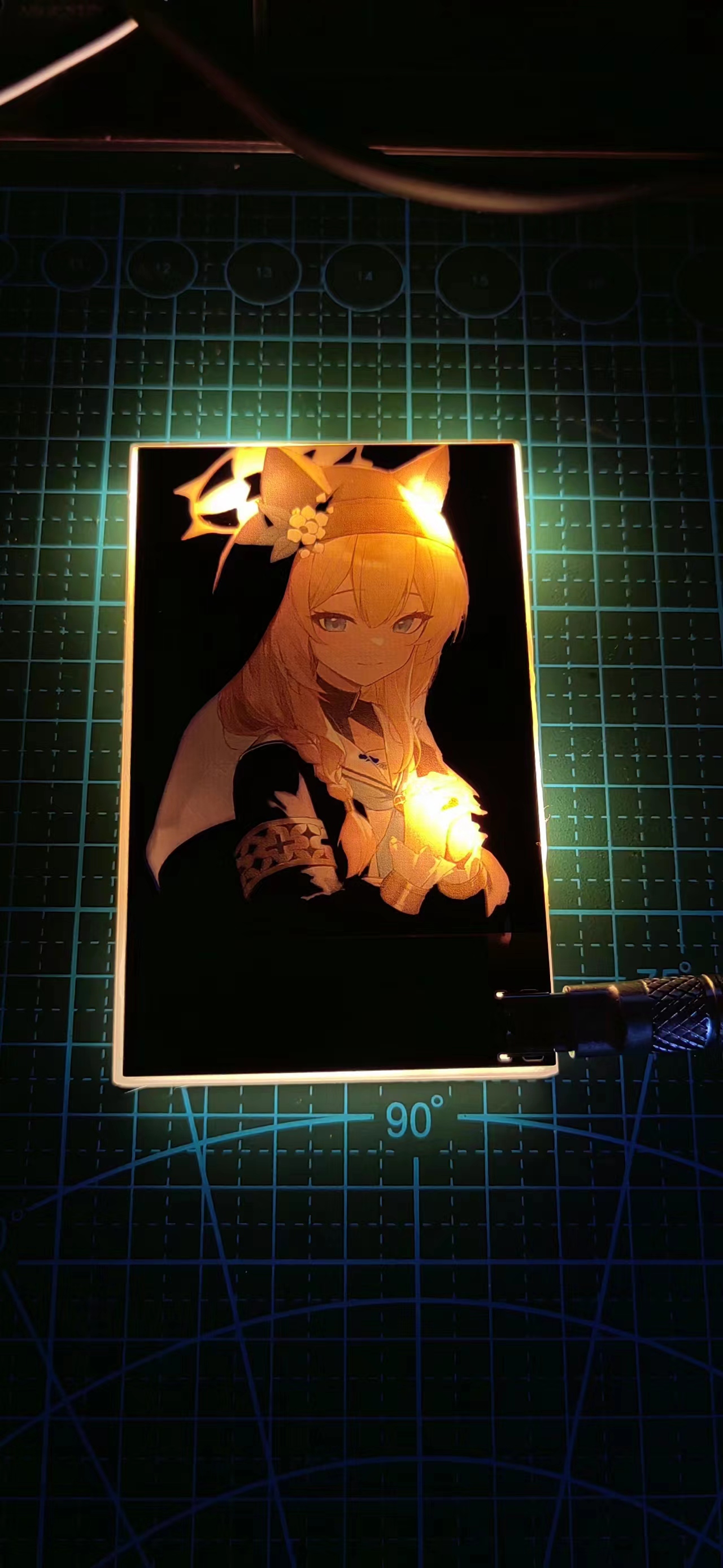
The original image and reflective cover are included in the accessories. If you're interested, you can try making a replica.
Bilibili video link: https://www.bilibili.com/video/BV1694y1573X/?spm_id_from=333.337.search-card.all.click&vd_source=6e36cb5877fc1084cf9aefe8f240bd03
Simplified version of the light painting stand.
Simplified version of the light painting casing.STL
PDF_Ilomarie's Colored Light Paintings.zip
Altium_Ilomarie's Colored Light Paintings.zip
PADS_Ilomarie's Colored Light Paintings.zip
BOM_Ilomari's Colored Light Painting.xlsx
97384
electronic


 京公网安备 11010802033920号

 SK-A2911


