 Hardware Introduction :
 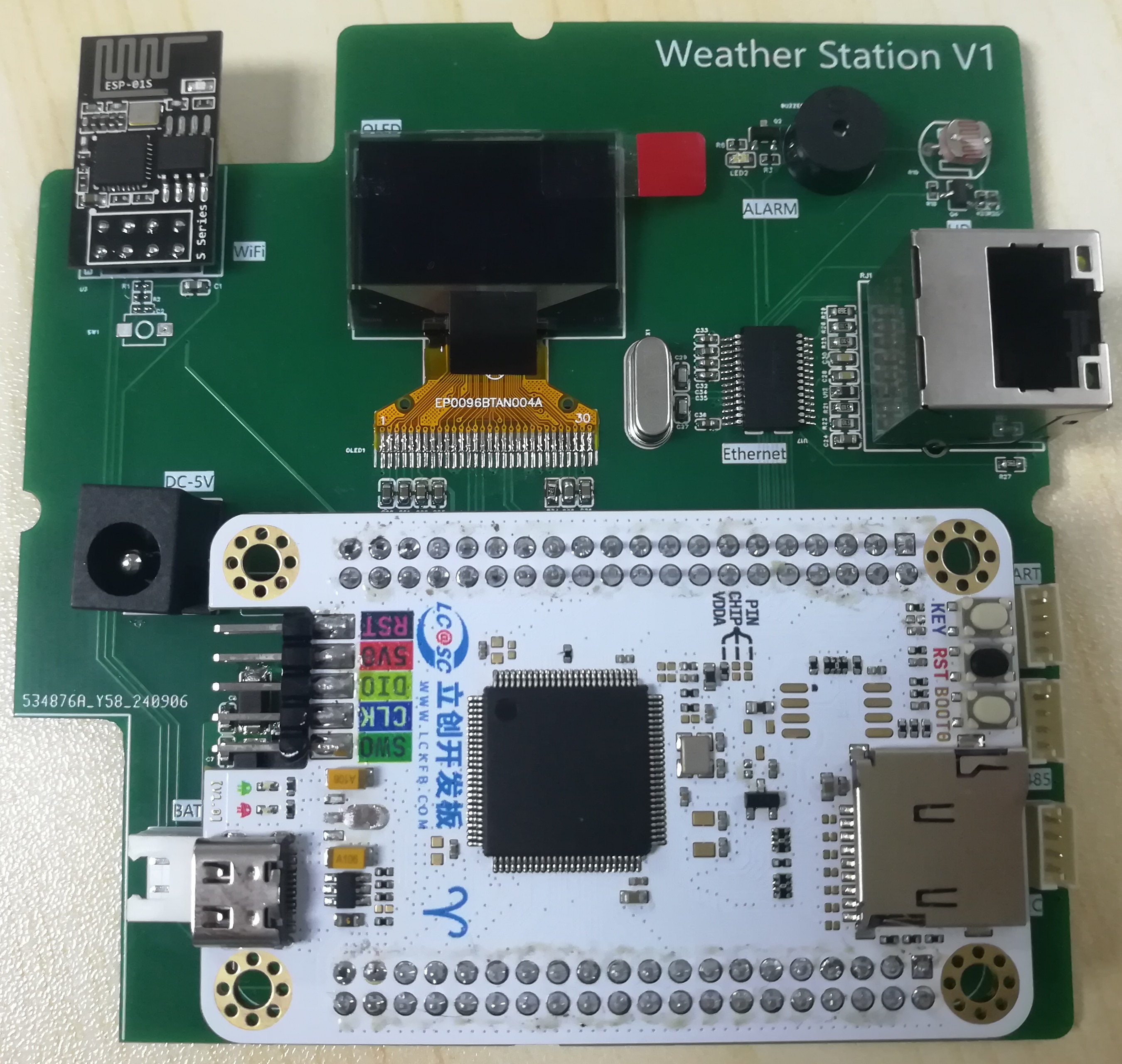 1. Power Supply Circuit
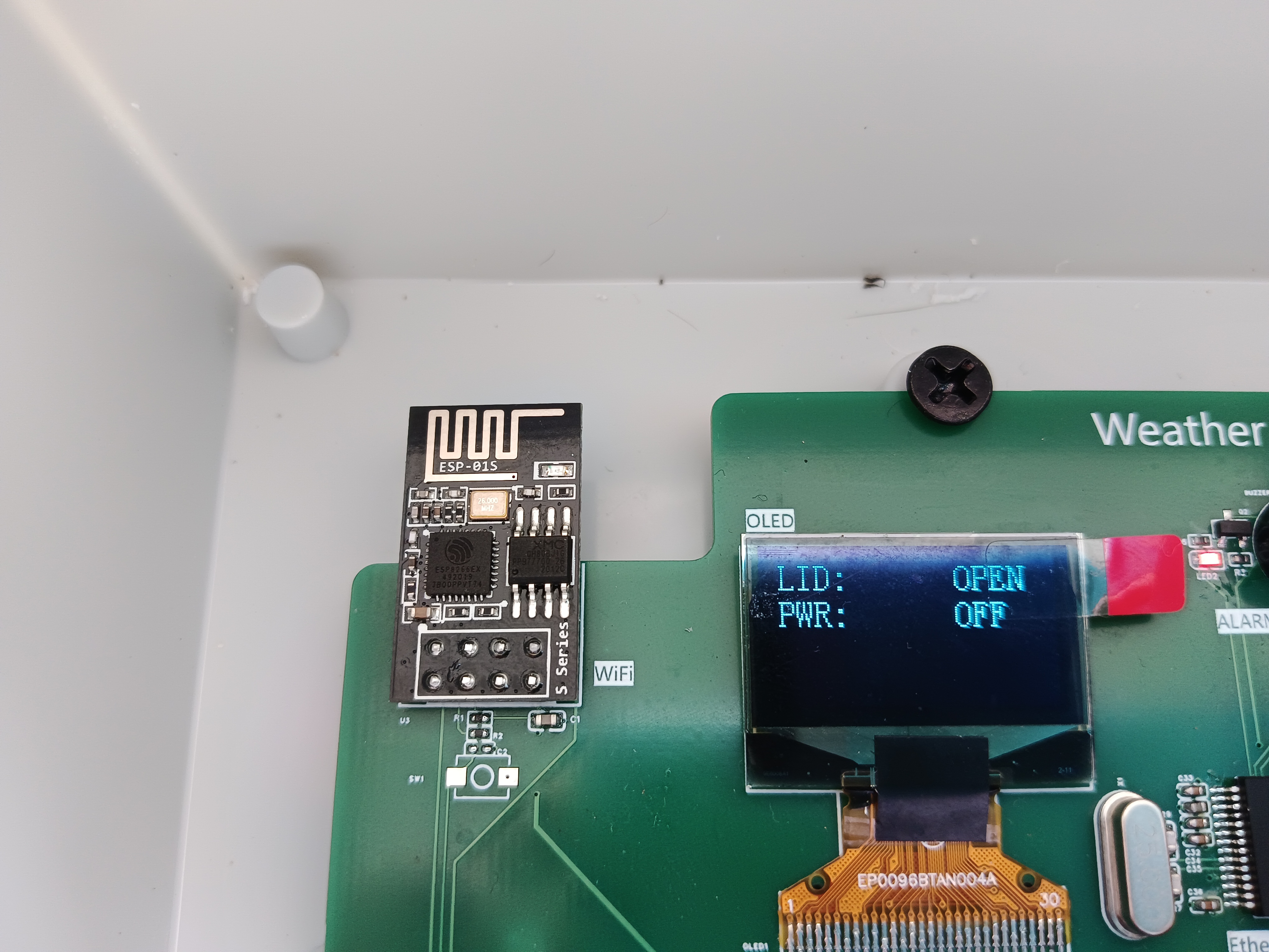
  This project is mainly powered by a DC 5V interface. The TYPE-C interface on the development board can also be used as a power supply interface, and a 12V lithium battery is provided as a backup power source. When external power is lost, the battery automatically discharges, the warning light flashes, the buzzer sounds, and the power failure information is sent to the cloud platform.
 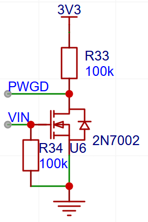 When there is an external power supply, VIN is high, and the PWGD pin reads a low level.
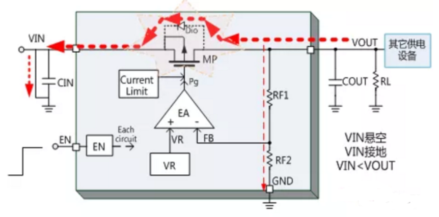 In this example, the 3.3V on the core board will flow back to VIN through 1117. When there is no external power input, there is still about 2.5V on VIN. Therefore, I removed 1117 from the core board to allow all 5V inputs to go to the baseboard before stepping down.
 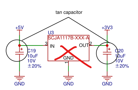 3. Step-down circuit:
 The 12V battery is reduced to 5V to power the PM2.5 module, and then the 5V is converted to 3.3V to power the system.
 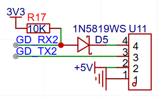 The PM2.5 module uses a 5V serial port and requires level conversion.
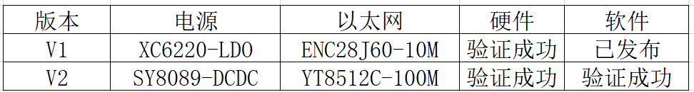
  Due to the small data volume in this project, SPI control of the ENC28J60 is used to achieve 10M Ethernet data transmission. The Ethernet is a maintenance interface and uses a fixed IP address. The connected computer needs to have its host IP address set to 192.168.1.x to ensure it's on the same network segment as the slave device.
  The product ID and device name can be viewed on the cloud platform, while the authentication information is calculated using OneNet's token generation tool.
 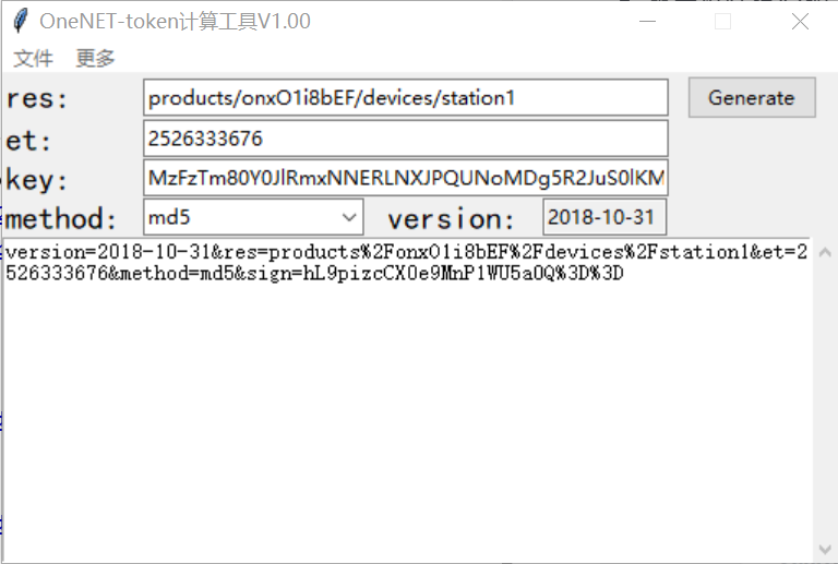 In the image, `res` is a fixed format; you only need to modify your product ID and device name. `et` is the device expiration time; change it to a timestamp greater than the current time. `key` is the device key from the device details; leave the rest as default. Click "Generate" to generate the authentication information. Then, replace the corresponding values in the code.
  The WiFi password and account in the image below are from my mobile hotspot; you can replace them with your own account or modify them to match the account shown in the image.
 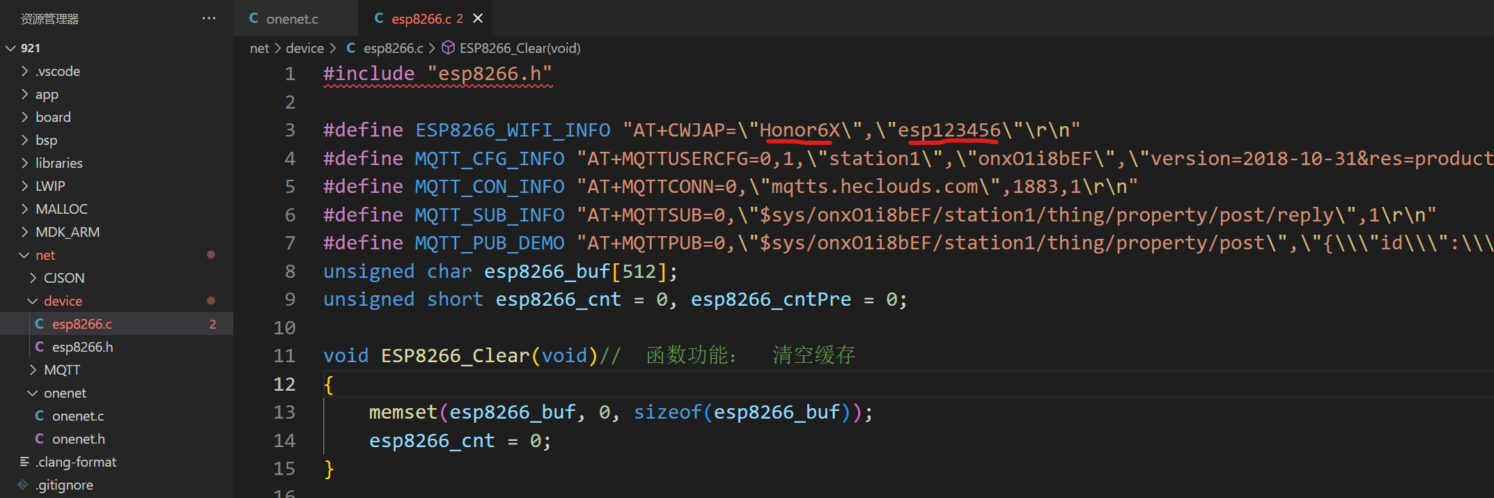 See the attachment for the specific code.
  2. Right-click and view properties, find IPv4, and click Properties
 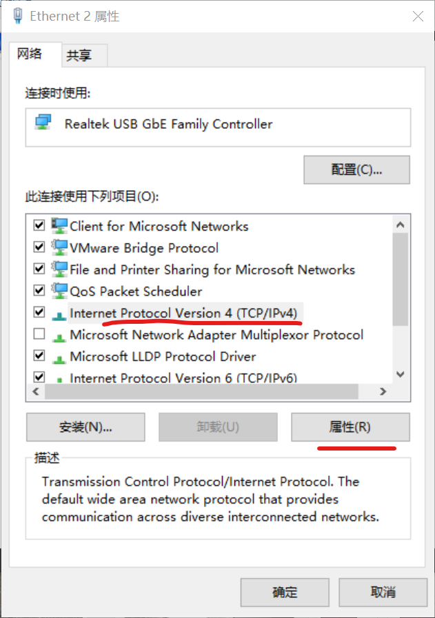 . 3. Change "Obtain an IP address automatically" to "Use a static IP address," and enter the IP address as shown in the image
  . 4. Open the control panel and type "ipconfig" to see that the device has been successfully configured.
 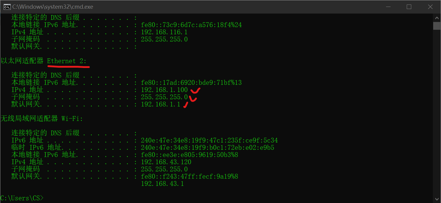 Assembly
 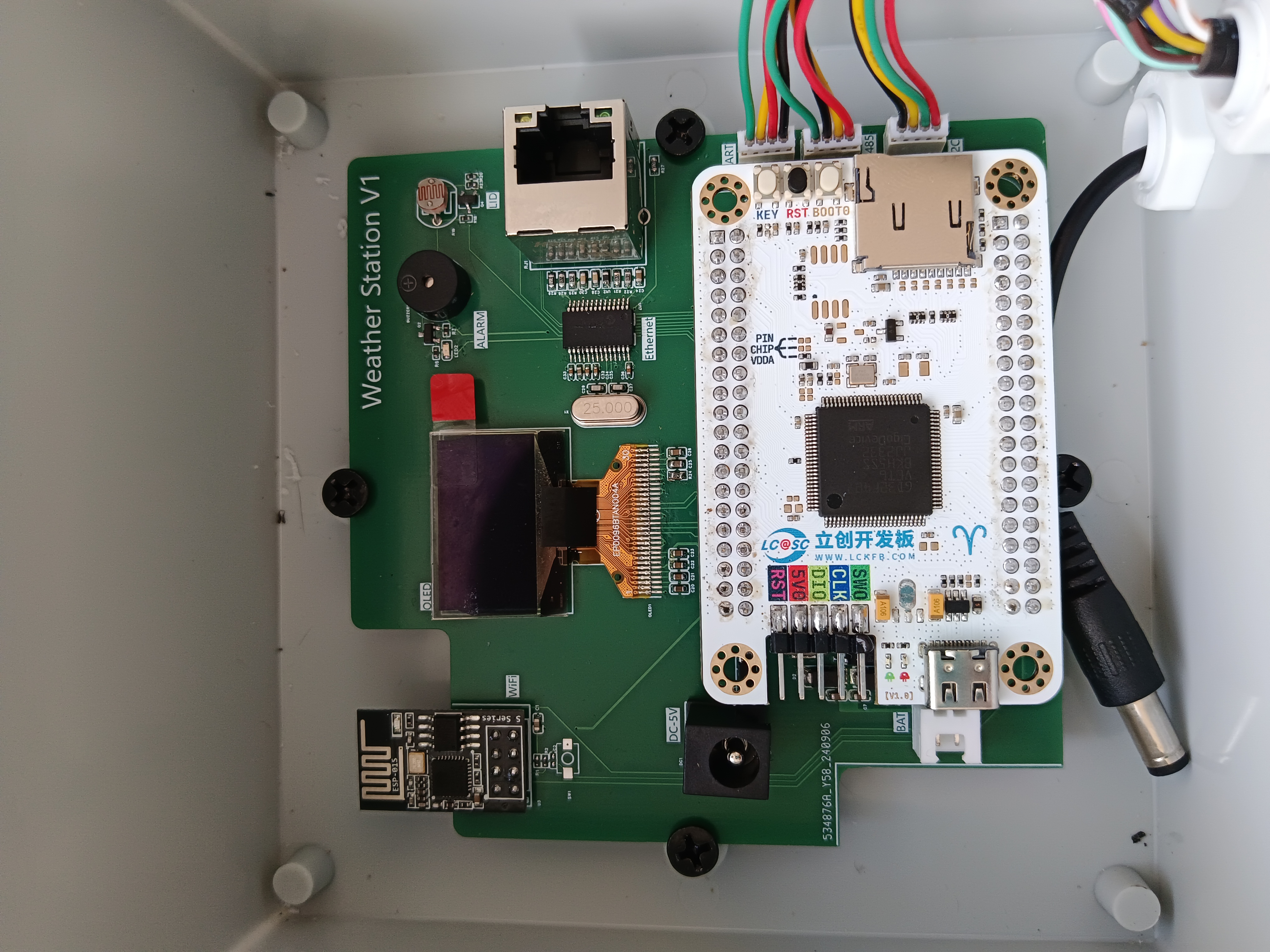 Figure 2: Install the wind speed, wind direction, rainfall, and louvered box onto a frame. I made a wooden frame for demonstration; you can also buy an iron frame. Drill a hole in the top of the louvered box and attach the light sensor to the top, ensuring a tight seal and waterproofing. Drill a hole in the bottom and run the 485 sensor wires into the louvered box, then connect it to the waterproof box via a bus. Figure 3: Function verification diagram
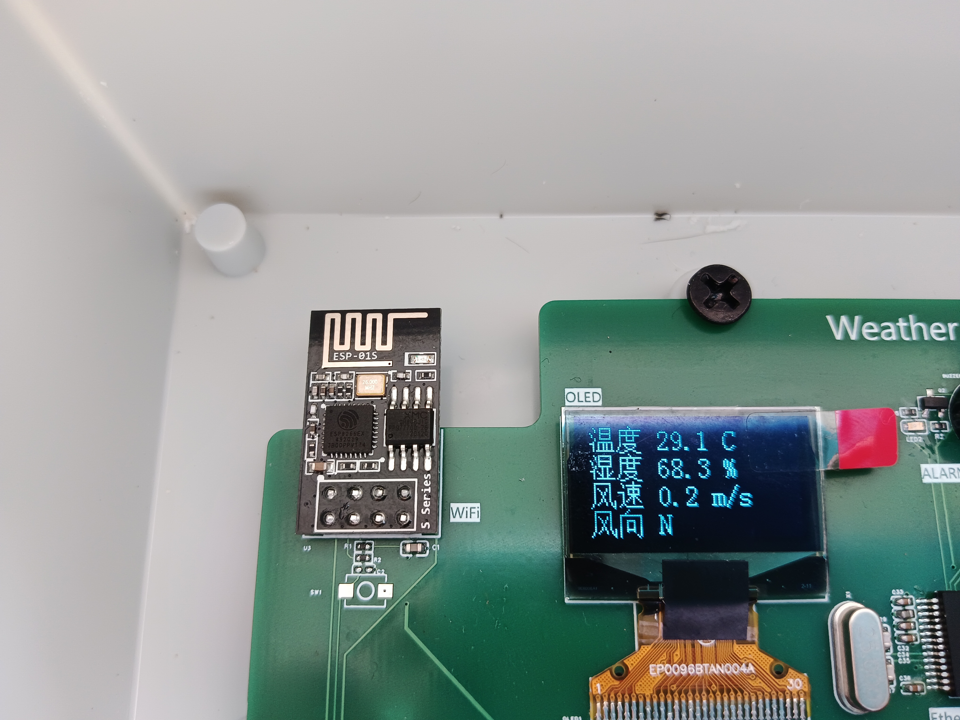
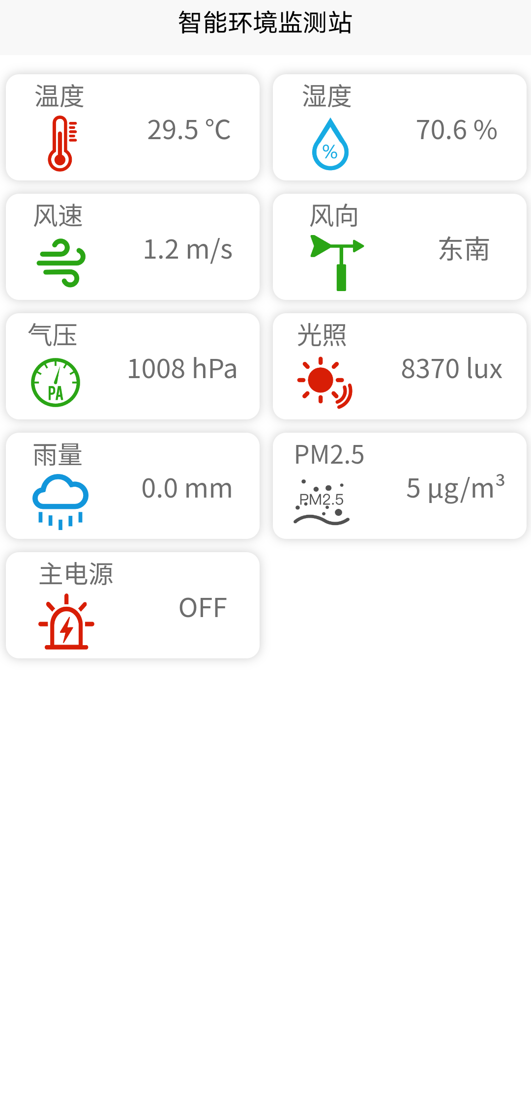
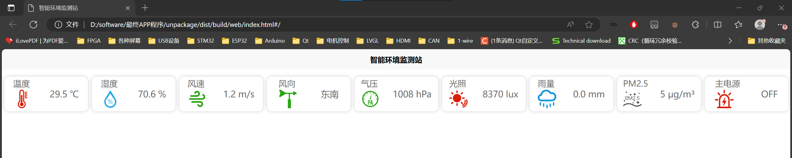
 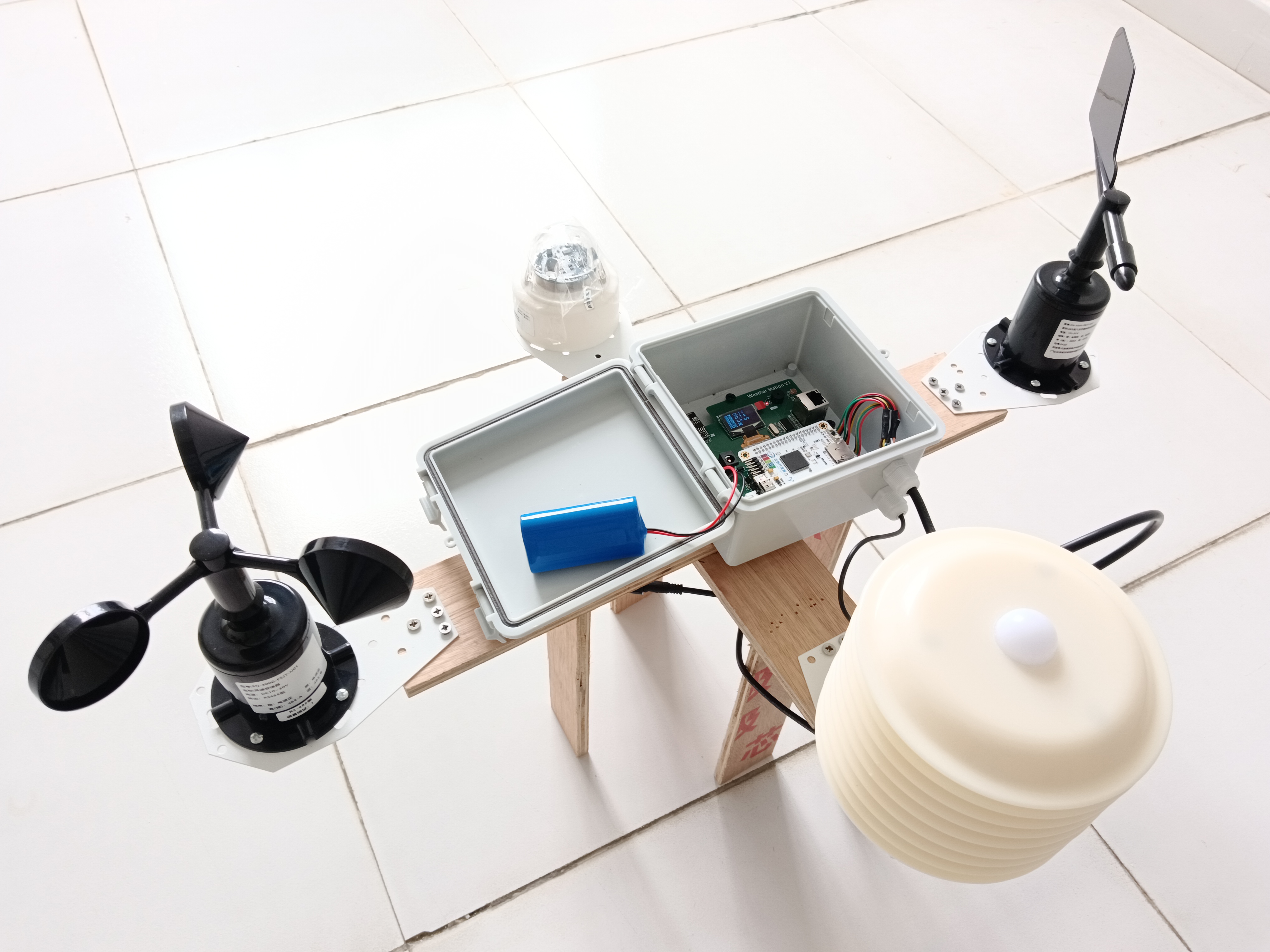 of sensor signal wiring table inside the waterproof box. Figure 1: The screen will print the initialization process upon power-on . Figure 2: View on local OLED screen. Figure 3: View on OneNet cloud platform. Figure 4: View on mobile APP. Figure 5: View on PC webpage. Figure 6: View on PC network port host computer. Video link: JLCPCB - Spark Program - Intelligent Environmental Monitoring System


All reference designs on this site are sourced from major semiconductor manufacturers or collected online for learning and research. The copyright belongs to the semiconductor manufacturer or the original author. If you believe that the reference design of this site infringes upon your relevant rights and interests, please send us a rights notice. As a neutral platform service provider, we will take measures to delete the relevant content in accordance with relevant laws after receiving the relevant notice from the rights holder. Please send relevant notifications to email: bbs_service@eeworld.com.cn.
It is your responsibility to test the circuit yourself and determine its suitability for you. EEWorld will not be liable for direct, indirect, special, incidental, consequential or punitive damages arising from any cause or anything connected to any reference design used.
Supported by EEWorld Datasheet
EEWorld
subscription
account

EEWorld
service
account

Automotive
development
community

Robot
development
community

About Us Customer Service Contact Information Datasheet Sitemap LatestNews


Room 1530, 15th Floor, Building B,
No.18 Zhongguancun Street,
Haidian District,
Beijing, Postal Code: 100190
China
Telephone: 008610 8235 0740
 京公网安备 11010802033920号

 PIC16LF84AT-04I/SSROM


