Version Notes:
Rev. 1
uses Xi'an Aerospace Minxin's BOOST chip MT3608 to provide VGH, VLED, and AVDD.
It uses Xinzhou Technology's SCT2450 to provide negative voltage VGL.
The VCOM correction circuit is provided by the screen datasheet.
A resistor divider scheme implemented by a foreign developer was used to convert TMDS33 to LVDS15 (see TMDS33 to LVDS - element14 Community).
Design flaws: The 1.5V voltage did not exceed the minimum voltage drop of the LED, failing to light the corresponding indicator light. This was not considered during the design process . Design flaws:
The orientation of the FPC was not taken into account, preventing the board from being mounted on the back of the screen as expected.
Not yet implemented: The power-on sequence required by the LCD screen is temporarily simulated manually using a switch.
Rev. 2
adds Texas Instruments' LM3880 for timing control, selecting a sub-model with a 2ms delay.
A small solid-state register is used to enable VGH and VGL.
The 1.5V indicator light has been removed
. 3.
Texas Instruments' TPS65150 was used to provide VGH, VGL, AVDD, and VCOM.
All voltage divider resistors used to determine the output voltage reference were replaced with variable resistors to adapt to other similar screens.
Since the TPS65150 has delay control, the LM3880 was omitted.
A socket layout adapted to the Atomic S6 core board was designed, which to some extent solved the interference caused by using DuPont wires during transmission.
LOG
2024.7.24: Rev.1 design completed.
2024.7.29: Rev.1 was verified, and the color bar driver based on Spartan6SLX16 was completed.
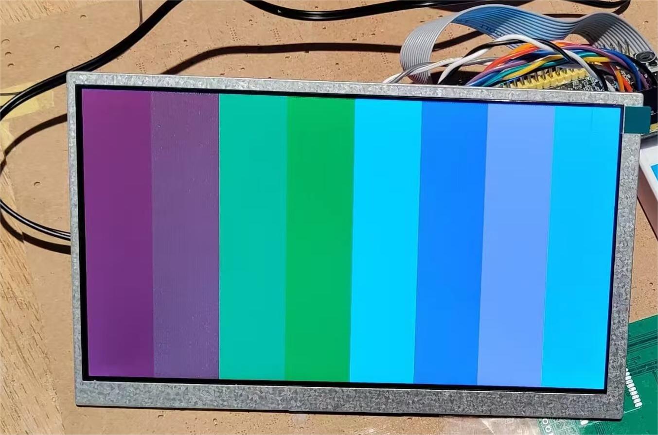
2024.7.30: It was found that colors containing red and green primary colors showed a large deviation when displayed on the LCD, accompanied by relatively dense speckles, while other colors displayed normally. A connection between the two LVDS signal channels was suspected. The connection problem was corrected by resoldering, but the above colors still could not be displayed normally (leaning towards green), and the speckles were still not resolved.
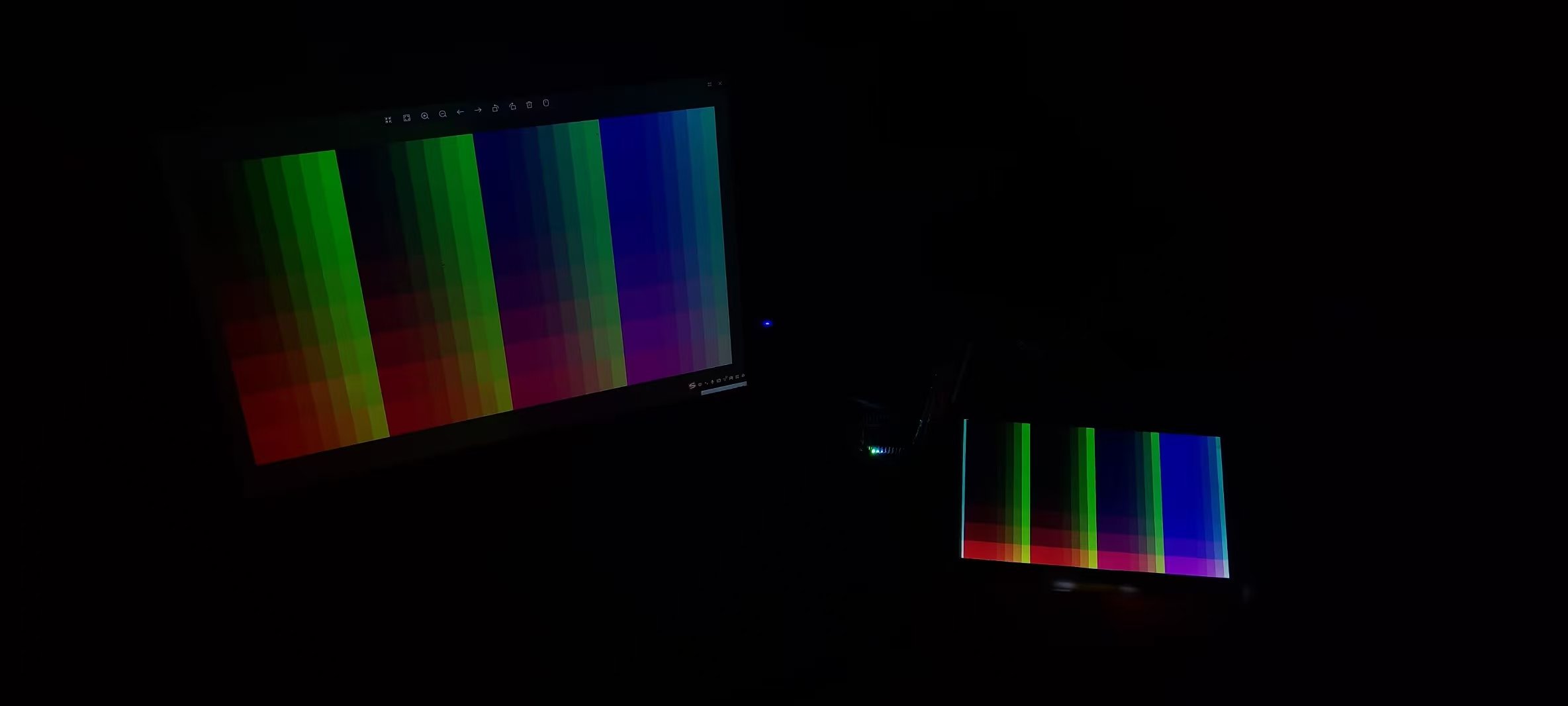
August 1, 2024: It was discovered that a 12-pixel display area on the far left of the screen should actually be on the far right. After attempts, it was found that this display misalignment could not be eliminated by modifying the timing or clock. The cause of this phenomenon is currently unknown. It is planned to discard the 12 pixels on each side in future use of this screen and use a 1000x600 resolution.

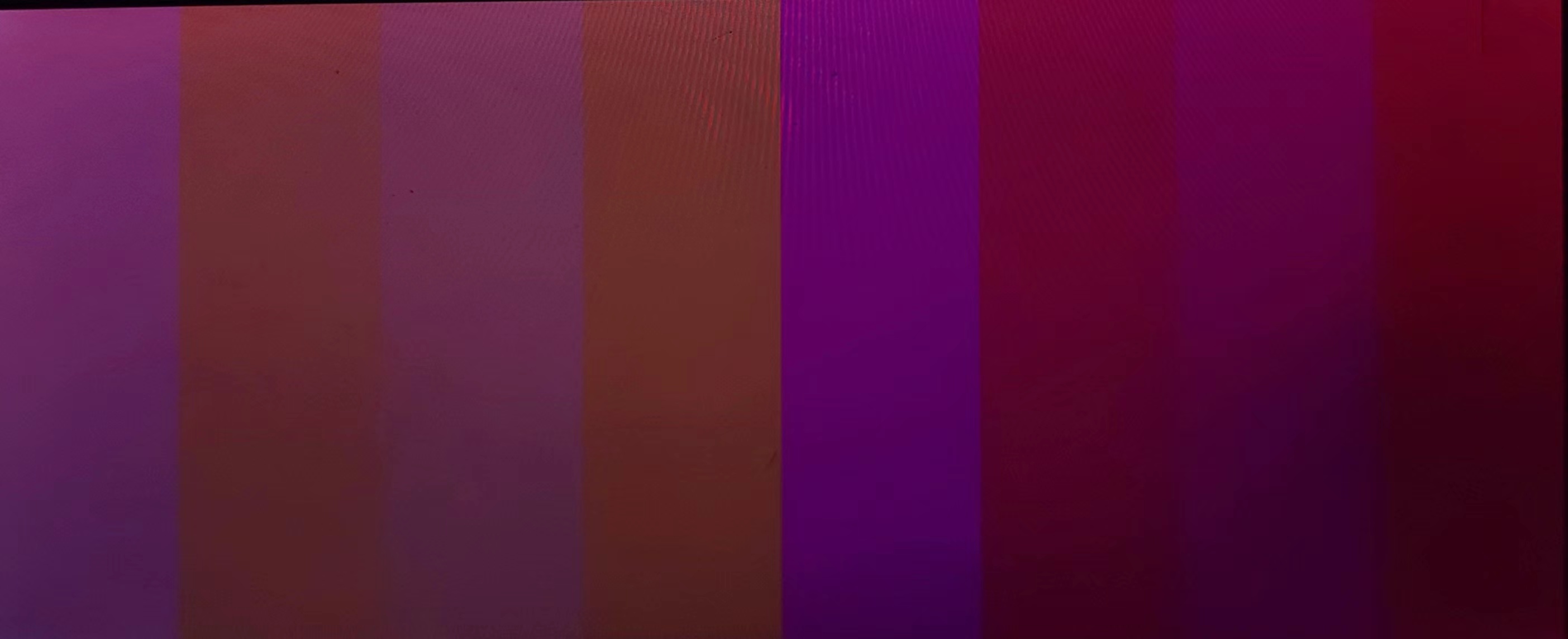
August 1, 2024: The serial-to-parallel conversion module was rewritten using the oserders2 primitives provided by Xilinx. The color deviation disappeared, but the speckling remains. Using the custom-written serial-to-parallel conversion module causes a "color mixing phenomenon" (as shown in the figure, the expected display is a color range from #F800 to #8800, which is significantly different from the actual displayed color). It is currently speculated that this is caused by the serial-to-parallel conversion module synchronously reading on the rising edge of the pixel, actually displaying an indeterminate state. The serial-to-parallel conversion module driven by the oserders2 primitives, due to the 90-degree amplitude lag between the serial-to-parallel conversion sampling and the pixel, displays correctly. The program is attached.
August 2, 2024: VGL was mistakenly connected before DVDD, and then VGH was connected, causing the screen to burn out (VLED wasn't connected at the time, but the screen clearly turned white and then wouldn't light up again).
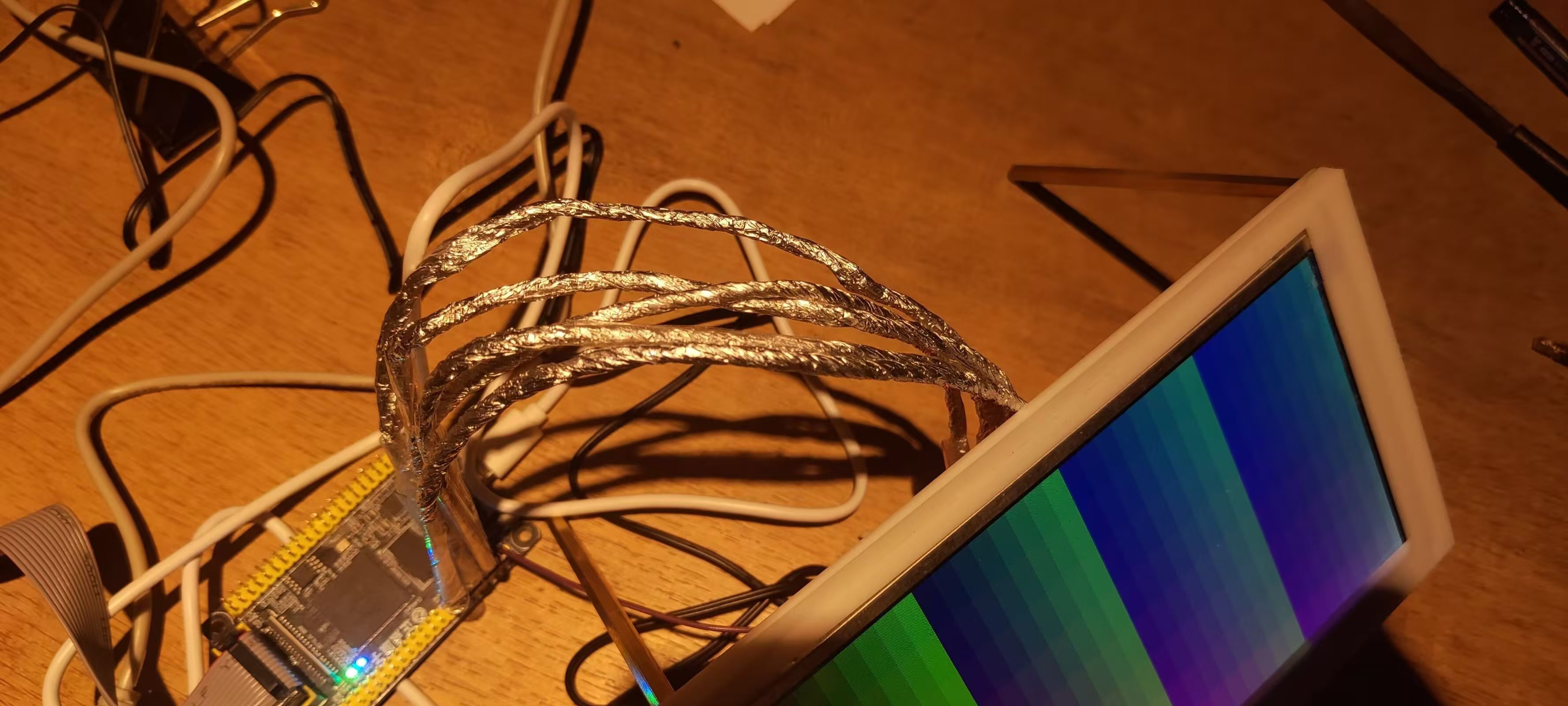
August 5, 2024: Inspired by a foreign developer (LCD panel + FPGA with an HDMI sink = External Display - element14 Community), I wrapped the twisted-pair cable with aluminum foil, temporarily solving the interference problem during signal transmission; the pitting almost disappeared.
August 8, 2024: Completed the schematic design for Rev.2.
August 10, 2024: During testing, I tried moving the transmission line and found that the discoloration and pitting reappeared. I tried restoring the transmission line to its original position, but it didn't improve the situation, suggesting a possible contact issue. I temporarily rejected the solution requiring connecting cables and decided to design an expansion board that can directly connect to the FPGA.
August 14, 2024: Completed the design for Rev.3.


 京公网安备 11010802033920号

 A54SX32-1VQ208M


