LM317 output voltage calculation formula, LM317 output voltage depends on what
Source: InternetPublisher:明天见 Keywords: lm317 output voltage Updated: 2025/02/20
LM317 output voltage calculation formula
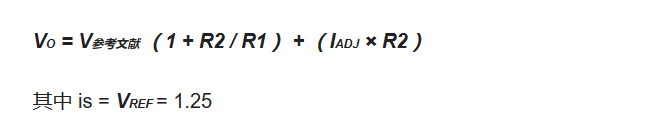
The current ADJ is practically negligible as it is typically around 50 μA and can therefore be ignored.
What does the LM317 output voltage depend on?
The output voltage of LM317 is determined by the ratio of resistors R1 and R2. Assume that R2 is a fixed resistor. Because the potential of the output terminal is high, the current flows into the ground point through R1 and R2. The control terminal of LM317 consumes very little current and can be ignored. Therefore, the potential of the control terminal is I x R2. Since the potential difference between the control terminal and the output terminal of LM317 is 1.25V, the voltage of Out (output) is:
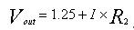
Next, calculate I: The potential difference between the out and adj pins is 1.25 V, and the resistor is R1. The current I is: 1.25/R1.

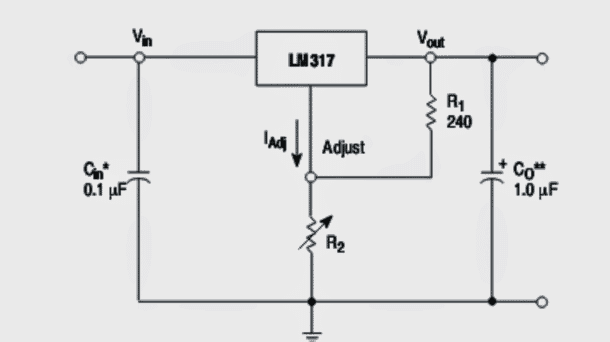
A standard LM317 variable voltage regulator circuit
The following image shows a standard IC LM317 variable voltage regulator circuit which uses minimum components in the form of a single fixed resistor and a 10K potentiometer.
This setup should provide a variable range of 24 to 30V with an input supply of 1V. However, if we consider the current range, it will never exceed 5.1 amps regardless of the input supply current, because the chip is internally equipped to only allow a maximum of 5.1 amps and suppress any request that might exceed this limit.
The design shown above is limited to 1.5
A maximum current, can be upgraded using an external PNP transistor in order to boost the current to a level comparable to the input supply current, meaning that once this upgrade is implemented the above circuit will retain its variable voltage regulation functionality but will be able to deliver the full supply input current to the load,
Bypasses the internal current limit function of the IC.
- Types and specifications of optocoupler ICs
- What affects the speed of high-speed operational amplifiers?
- Which one is better, NPN or PNP transistor?
- What is a Half Wave Rectifier? Working Principle of a Half Wave Rectifier
- What is a pure resistance circuit? What is a pure resistance AC circuit?
- Ideal characteristics of operational amplifiers/pin configurations/gain types/primary applications
- The Importance and Ideal Model of Impedance Matching
- TL494 pin functions/configuration/ratings/operating conditions/layout diagram
- Important things to know about PCB routing and how to design the right routing for your PCB
- How to build a triangle wave generator using an op amp and discrete components
- Thermocouple Cold Junction Compensation Amplifier
- Typical relaxation oscillator and its output voltage waveform
- Shandong GD36 charger circuit
- Basic regulating tube voltage stabilizing circuit a
- Output voltage expansion circuit a
- WYJ81 type automatic AC regulated power supply circuit
- Output 85 to 145V adjustable regulated power supply circuit
- Bipolar regulated power supply circuit using SW1468 voltage regulator block 2
- Basic application circuit of LM31703
- Practical regulated power supply circuit diagram using LM317


 京公网安备 11010802033920号