The circuit shown in Figure 1 provides two 16-bit, fully isolated, general-purpose analog input channels suitable for programmable logic controller (PLC) and distributed control system (DCS) modules. Both channels support software programming, as well as a variety of voltages, current ranges, thermocouples, and RTD types, as shown in Figure 1. Input channels are protected against ±30 V DC overvoltage conditions.

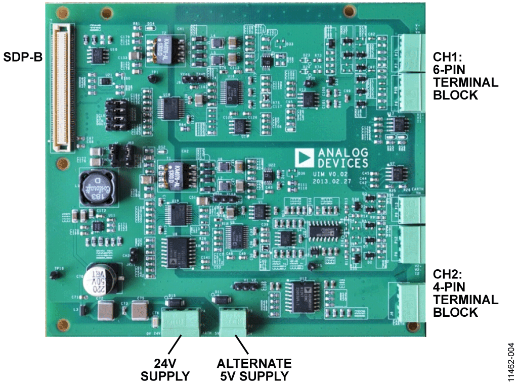
The demo board contains two different fully isolated universal input channels, one with a 4-pin terminal block (CH2) and one with a 6-pin terminal block (CH1). For the 4-pin terminal board (CH2), the voltage, current, thermocouple, and RTD inputs all share the same 4 terminals, minimizing the number of terminal pins required. For the 6-pin terminal board channel (CH1), the voltage and current inputs share one set of 3 terminals, and the thermocouple and RTD inputs share another set of 3 terminals; this requires more terminals but results in lower device count and component cost Also lower. Figure 2 shows a photo of the PCB and Figure 3 shows a detailed schematic of the circuit.


The AD7795 low-noise, 16-bit Σ-Δ ADC features an on-chip instrumentation amplifier and voltage reference for data conversion applications. On-chip instrumentation amplifiers and current sources provide a complete solution for RTD and thermocouple measurements. For voltage and current inputs, the AD8226 instrumentation amplifier (which has a CMR greater than 90 dB) is used to provide high input impedance and reject common-mode interference. A precision resistor divider scales the voltage and current signals into the range of the ADC.
The ADR441 is an ultra-low noise, low dropout XFET® 2.5 V reference used as the reference for ADCs.
For the 4-pin terminal block channel (CH2), use the ADG442 , low R ON anti-latch-up switch to switch between voltage, current, thermocouple, and RTD input modes.
The ADuM1311 three-channel digital isolator is also used in the 4-pin terminal block circuit to isolate the control lines of the ADG442 switch. Digital and power isolation is achieved using the ADuM3471 , a PWM controller and transformer driver with a quad isolator for generating ±15 V isolated power from an external transformer.
The ADP2441 36 V step-down dc-to-dc regulator has a wide input supply tolerance, making it ideal for accepting 24 V industrial voltages. Accepts power supplies up to 36 V, which facilitates reliable transient protection of power inputs. The ADP2441 reduces the input voltage to 5 V to drive the ADuM347 and all other control side circuits. The circuit also provides external protection on the 24 V supply side.
The ADP2441 also has various other safety/reliability features such as undervoltage lockout (UVLO), precision enable feature, power good pin, and overcurrent limit protection. Efficiencies up to 90% can also be achieved in a 24 V input, 5 V output configuration.
hardware
Figure 2 shows the channel location with a 4-pin terminal block and the channel location with a 6-pin terminal block. Also shown is the location of the 24 V power input.

Channel selection
Jumpers need to be inserted and switched to configure the power and SPI signals between CH1 and CH2, as shown in Table 1.
| link number | Digital functions | Select the link bit of CH1 (6-pin terminal board) | Select the link bit of CH2 (4-pin terminal board) |
| JK0 | 5V power supply | CH1 | CH2 |
| JK1 | SCLK | CH1 |
CH2 |
| JK2 | /CS | CH1 |
CH2 |
| JK3 | Din | CH1 |
CH2 |
| JK4 | Dout | CH1 |
CH2 |
| JK11 | TEMP_CS | not inserted | inserted |
Power configuration
Use a 24 V supply to drive the controller side of the evaluation board. A 5 V supply can also be used to bypass the ADP2441 circuit. This 5 V input does not have any overvoltage protection and must not exceed 6 V. The power supply used should be configured through the J4 link option as shown in Table 2.
| Select the link bit for 24V input (default) | Select the link bit for 5V input (default) | |
| J4 | VCC1 | VCC2 |
For the analog inputs of the isolation barrier, there are two options for a regulated 5 V supply that drives the analog circuitry. The ADP1720 linear regulator can be used to step down the 15 V supply to 5 V, or the ADuM3471's built-in 5 V regulator can be used. The link configurations for both options are shown in Table 3.
| Link bits for ADP1720 5V regulator (default) | Link bits for the ADuM3471 5V regulator | |
| J3 | Vreg | Vaum |
| J9 | Vreg | Vaum |
CH2: 4-pin terminal board channel
input connector

voltage and current
The P12 connector is used for voltage and current input connections. Figures 11 and 12 show simplified schematics of this input connection and configuration. Supported differential input ranges are: 0 V to 5V, 0 V to 10V, ±5V, ±10 V, 0 mA to 20 mA, 4 mA to 20 mA, and ±20 mA. Connect a voltage or current input between V1+ and V1– because a current input will short the V1+ and I1 pins together at the same time. This connects a 249 Ω precision current sense resistor with 0.1% accuracy and a 0.25 W rating.
Thermocouple
The P12 connector is also used for thermocouple input. Several thermocouple types can be connected, including J, K, T and S. The thermocouple is connected between the V1+ and V1- inputs (Figure 5). Figure 6 below shows how to connect a thermocouple (for example, Type T) to a universal analog input board. A simplified schematic of the thermocouple input is shown in Figure 13.

RTD
P12, P13 connectors are used for RTD input. The hardware can support 1000 Ω and 100 Ω platinum RTD inputs. For 3-wire mode, the two common wires are connected to V1+ and V1–, and the loop is connected to Vm (see Figure 5). Figure 7 below shows how to connect a 3-wire RTD sensor to a universal analog input board. A simplified schematic of the RTD input is shown in Figure 14.

CH1: 6-pin terminal board channel
input connector

voltage and current
The P10 connector is used for voltage and current input connections. Supported differential input ranges are: 0 V to 5 V, 0 V to 10V, ±5V, ±10V, 0 mA to 20 mA, 4 mA to 20mA, and ±20 mA. Connect a voltage or current input between V1+ and V1– (see Figure 13), although for current inputs also short the V1+ and I1 pins together, thus connecting a 249 Ω precision current sense resistor. Accuracy is 0.1% and rating is 0.25 W.
Thermocouple
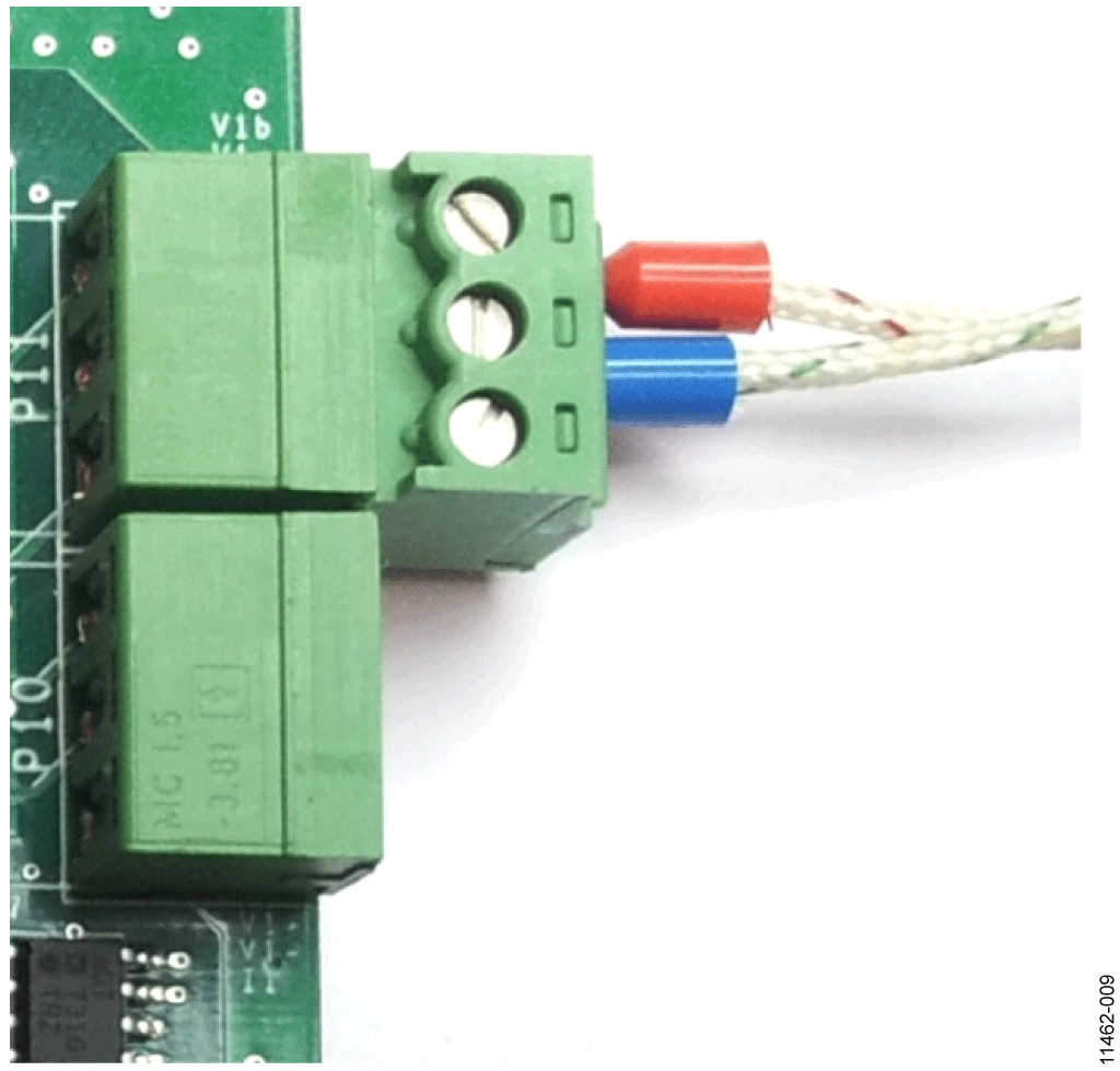
P11 connector is used for thermocouple input. Several thermocouple types can be connected, including J, K, T and S. The thermocouple is connected between the V+ and V- inputs (Figure 8). Figure 9 below shows how to connect a thermocouple (Type T in this case) to a universal analog input board.

RTD
The P11 connector is also used for RTD input. The hardware can support 1000 Ω and 100 Ω platinum RTD inputs. For 3-wire mode, the two common lines are connected to V+ and V–, and the loop is connected to Vm (see Figure 8). Figure 10 below shows how to connect a 3-wire RTD sensor to a universal analog input board.

Simplified input circuit diagram


See the CN0325 PDF file for a description of software operation .


Blockdiagram
All reference designs on this site are sourced from major semiconductor manufacturers or collected online for learning and research. The copyright belongs to the semiconductor manufacturer or the original author. If you believe that the reference design of this site infringes upon your relevant rights and interests, please send us a rights notice. As a neutral platform service provider, we will take measures to delete the relevant content in accordance with relevant laws after receiving the relevant notice from the rights holder. Please send relevant notifications to email: bbs_service@eeworld.com.cn.
It is your responsibility to test the circuit yourself and determine its suitability for you. EEWorld will not be liable for direct, indirect, special, incidental, consequential or punitive damages arising from any cause or anything connected to any reference design used.
Supported by EEWorld Datasheet