
Abstract
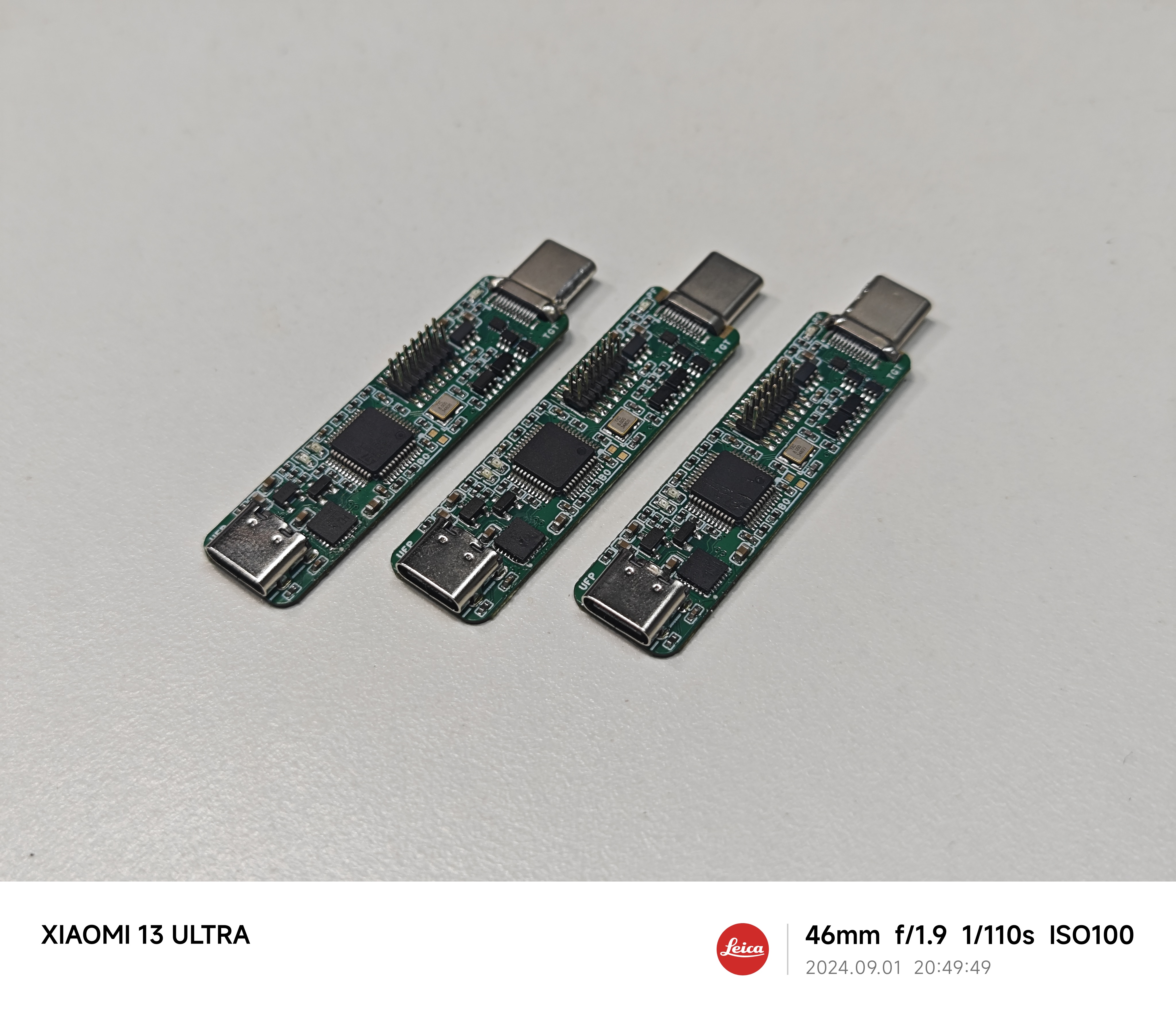
This paper proposes an ST-LINK/V2-1 wiring scheme based on the Type-C interface debug accessory mode. It achieves simultaneous support for SWD debugging, VCP virtual serial port, and downstream USB debugging functions with a single connection, and supports reversible insertion, significantly improving convenience compared to traditional connection methods. To verify the feasibility of the scheme, a PCB was designed based on the STM32F103CBT6 and CH334F, validating the design. The designed PCB, in addition to the proposed one-line Type-C male connector, provides a small-size standard STDC-14 debug interface for ST-LINK/V3 Minie power supply and implements overcurrent and reverse current protection for downstream power supply, demonstrating practical value. Finally, this paper provides detailed schematics, PCB design, and BOM for readers' reference.
Introduction
When designing a microcontroller minimum system, the design of the debug interface significantly affects the PCB layout and debugging convenience. Common debug interface designs based on pin headers, test points, etc., suffer from the following problems:
large size, occupying PCB space,
requiring dedicated ribbon cables or probes to connect to the debug interface
, inconsistent pin order requiring repeated reference to pin definitions and DuPont wire connection (time-consuming and laborious), easy to connect incorrectly,
insufficient protection measures for the 5V or 3V3 power supply provided by the debugger (potentially causing backflow into the computer's USB interface) , and
the debug interface being enclosed inside the development board, requiring additional openings on the casing.
While the design of integrating ST-LINK on the development board, as used in the official STM32 Discovery series development boards, improves the convenience of connecting to the computer, an additional USB cable is needed to connect to the development board if the MCU's USB function is required simultaneously. Furthermore, the onboard ST-LINK design significantly increases the development board's area and cost.
The solution proposed in this paper reuses the Type-C interface on the development board, achieving SWD debugging, VCP virtual serial port, and downstream USB connection with a single connection without any additional area or components. The MCU being debugged only needs a common, inexpensive 12/16-pin Type-C interface to simultaneously use SWD debugging and USB functionality, supporting reversible insertion. If the development board does not require USB functionality, the USB data cable can be reused as a VCP virtual serial port, and the debugger can automatically recognize the USB reused as VCP. If the development board uses a 24-pin Type-C interface, SWD debugging, VCP virtual serial port, and USB functionality can be performed simultaneously. For the 24-pin interface, the routing on the debugger side has been optimized, reducing the complexity of routing fan-out on the development board side.
It is worth noting that, based on the Debug Accessory mode defined by the Type-C specification, the Type-C debug port on the development board can also be used as a regular USB data interface, and the development board can detect whether a debugger or a regular USB cable is connected to the debug interface, thus allowing for more application scenarios. The JTAG interface, a standard feature
in relevant work
, and the large 20-pin Simplified Adapter on the genuine ST-LINK V2 are examples of improving the wiring experience through standardized debug interface pin definitions. However, the 20-pin connector is simply too large and unsuitable for small development boards. The ST-Link V3 series' STDC-14 debug interface significantly reduces size compared to the 20-pin Simplified Adapter; however, the risk of reverse connection still exists on the development board side, and the cheapest (but still expensive) ST-LINK/V3 Minie cannot provide downstream power. The STLINK from GeekSTM32 Electronics Development Network is inexpensive and can be directly connected to their designed development boards via a 7-pin 2.54mm header; however, the double-layer header design also carries the risk of reverse connection, and a considerable amount of extra space on the development board is required for the debug interface. The

minoseigenheer debug pin design,
based on a Type-C interface debug accessory mode, provides an SWD over USB-C solution that enables SWD debugging and downstream USB via the Type-C interface, serving as one of the inspirations for this paper. However, this solution lacks VCP virtual serial port functionality and requires a 24-pin Type-C interface on the development board, increasing cost and wiring complexity.
This solution addresses this by adjusting the Rd pull-down resistor values on the two CC lines within the specified tolerance range on the development board side. This allows detection of the female insertion direction from the male side (instead of the usual female side), enabling the reversal of the pinout on the debugger side. This allows for two-wire debugging of SWDIO and SWCLK using the two SBU pins. Furthermore, based on the detection of the Rd pull-down resistors, the analog switch can be controlled to switch D+ and D- for USB or VCP serial port use, providing as many functions as needed on the 16-pin Type-C interface.
The

Type-C specification requires that the receiving end (Sink) have 5.1kR pull-down resistors, referred to as Rd, connected to both CC1 and CC2; the supply end has pull-up resistors or current sources of a certain value, Rp, connected to both CC1 and CC2 to pull the voltage on the CC line to a certain value. Different voltage levels on the CC line indicate the maximum current that the receiving end is allowed to draw during the initial connection establishment. Since a correct CC connection only allows connection to one side of the CC pin, the other CC pin must either be open or have a 1kR pull-down resistor Ra to enable VCONN power. Therefore, the connection status of Rp, Rd, and Ra on the two CC lines can distinguish the type of connected device and the insertion direction.
CC1
CC2
Status
Rp Rd Not Connected
Rp Rd Not Connected
Rp
Rd Not Connected
Rp-Rd 0.25V-2.04V
Connect to device using ordinary cable
Rp-Rd 0.25V-2.04V
Rp Rd Not Connected
Connect to device using ordinary cable
Rp-Ra -0.25V-0.15V
Rp-Rd 0.25V-2.04V
Connect to device using E-Marker cable, CC1 is VCONN
Rp-Rd 0.25V-2.04V
Rp-Ra -0.25V-0.15V
Connect to device using E-Marker cable, CC2 is VCONN
Rp-Rd 0.25V-2.04V
Rp-Rd 0.25V-2.04V
Debug Accessory Mode
Rp-Ra -0.25V-0.15V
Rp-Ra -0.25V-0.15V
audio accessory mode
Different voltages on the Rp-Rd connection can also distinguish power supply capabilities. Therefore, the Type-C interface can differentiate the types and insertion orientations of various connected devices without transmitting PD messages, enabling debug accessory mode. As shown in the table above, since a standard Type-C connector has only one CC pin on the male side, debug accessory mode requires a specially designed male connector directly connected to the female port. The development board's female port controls the Mux to change the wiring by detecting whether both CC pins simultaneously have vRd-Connect voltage to indicate a debug accessory connection. (In the case of using only USB 2.0, the solution in this paper does not require detection and can be directly connected).
A standard Type-C debug accessory mode allows pins 2, 3, 6, 7, 8, 10, and 11 (7 pins in total) to be used to transmit custom debug signals without insertion orientation detection. However, this requires the connector to have a 24-pin Type-C interface, and the wiring on the development board side is more complex. A simple 16-pin Type-C interface only uses pins 6, 7, and 8. If USB functionality is retained and no additional components are added to the development board, only pin 8 (SBU pin) is actually usable. Therefore, insertion orientation detection must be implemented to transmit the SWDIO and SWCLK signals on pins A8 and B8 respectively.
Type-C insertion orientation detection and pin sequence reversal are typically performed on the female side, but to avoid adding components to the female side, this paper places them on the male side. The Type-C specification provides a large tolerance range for the Rd resistor. By using slightly different Rd resistors on both sides of the female side and the same Rp resistor on the male side, a comparator can compare the voltages on the two CC lines to determine the insertion orientation of the female side. Then, an analog switch can be used to swap the pin sequence of the SWDIO and SWCLK signals without requiring firmware modifications to the debugger. The two SBU pins on the development board can be directly connected to the MCU without requiring additional components.
The above design allows simultaneous use of SWD debugging and USB functionality on a 16-pin Type-C port. For development boards that do not support or require USB functionality, can the USB data line be reused as a USART serial port? This is possible. Due to the complex voltage levels of USB D+ and D- and USART, a comparator is used to detect the voltage divider resistor of CC1 to switch the analog switch, achieving USB and VCP multiplexing. For the complete 24-pin female port, VCP and the remaining debugging signals are brought out from the high-speed signals on both sides. The additional signals are double-sided on the debugger male connector side, so the development board female port side only needs a single-sided connection, reducing the wiring difficulty on the development board side.
The USB section incorporates a small-package CH334 Hub, enabling simultaneous connection of the debugger and development board to the host computer in a single cable. The STDC-14 debug interface utilizes an undefined pin to add 5V power supply and is protected by a TPS2553 chip to prevent overcurrent and reverse flow. A red LED next to the USB male connector indicates a power supply failure. The overcurrent protection current is designed to be 1.5A, which basically meets most needs and can be adjusted. (Note: Genuine ST-LINK/V2-1 firmware has the function of controlling the load switch using GPIO pins, which can limit the current to 100mA during the initial USB handshake to meet the USB specification. In fact, almost all USB interfaces do not strictly implement the 100mA limit, so this function is not implemented in this design.)
Experiments and discussions
have verified that this debugger can be flashed with ST-LINK/V2-1 firmware and works normally, supporting reversible insertion. DAPLink firmware can be flashed and recognized by the host computer PyOCD, but the SWD debugging function has not yet been tested. Short circuit protection and reverse current protection functions have been verified, and the LED lights up when there is a power failure. The following are precautions:
CH334 crystal-free function: In order to save PCB space, this design needs to use the internal crystal oscillator of CH334. Although, according to replies 1 and 2 on the Qinheng forum, the latest CH334 chipsets, except for the CH334S package, all support crystal-free functionality, as of September 2024, the LCSC surface-mount CH334F does not support crystal-free operation and cannot function properly. However, the CH334F sold by this Taobao store in August 2024 does support crystal-free operation. This design has two versions, CH334F and CH334P; it is recommended to confirm with the seller whether crystal-free functionality is supported.
STM32 Capacity: Please use a 128kB STM32F103CBT6; otherwise, ST-LINK/V2-1 firmware cannot be flashed. Other domestic alternative chips are theoretically feasible, but have not been tested.
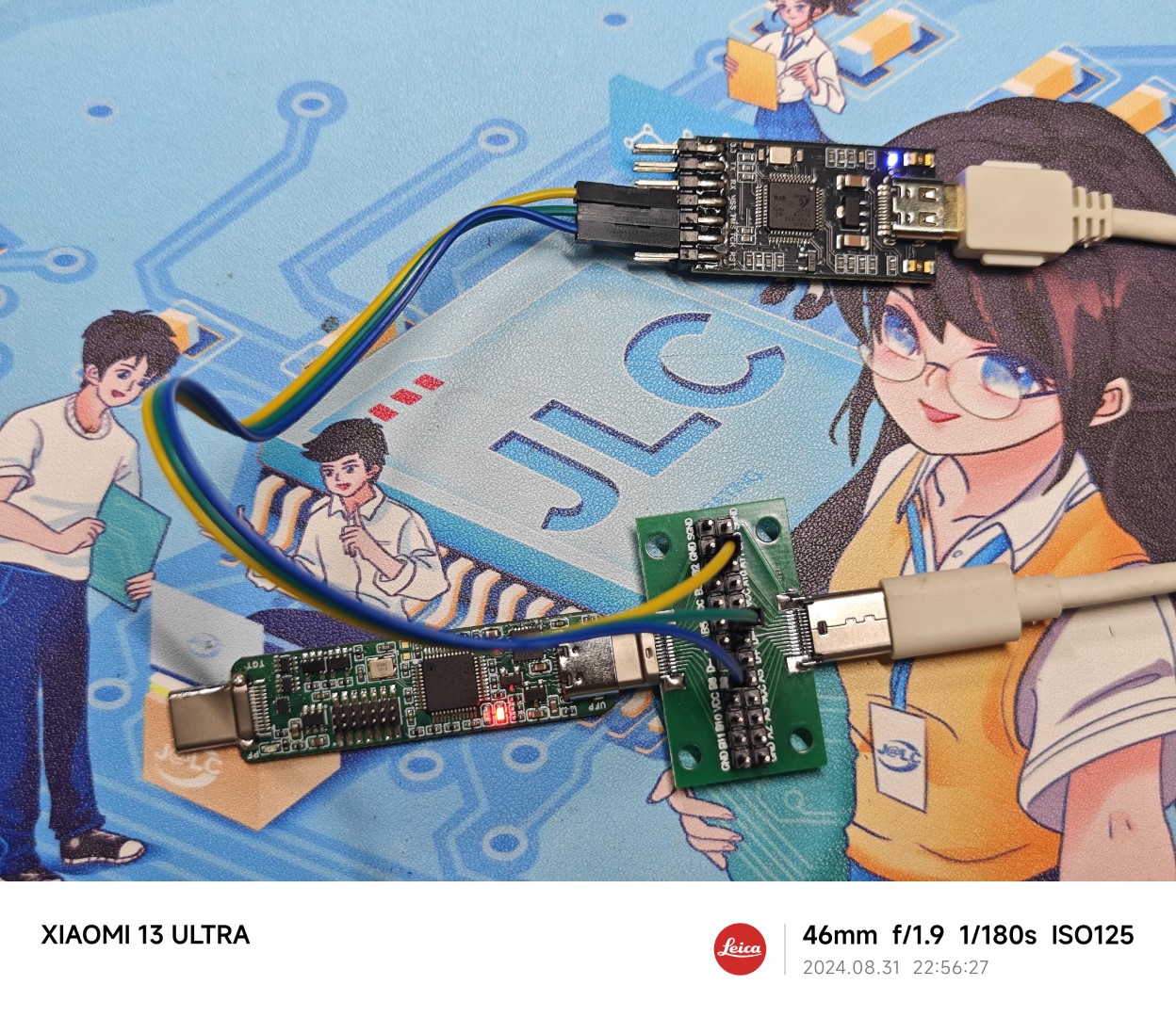
Firmware Flashing Method: The debugger's own SWD debugging interface also uses a one-line solution to connect to the host computer's Type-C female connector. When building your first debugger, you can purchase a Type-C male/female connector test board. Connect the test board to your computer using the female connector on the debugger, and then use a regular ST-LINK firmware to flash it.
Before wiring, connect the ground wire, then use a multimeter in voltage mode to measure the voltage of pins A5, A8, B5, and B8 on the test board. The pin with 3.3V is SWDIO, and the pin diagonally opposite SWDIO is SWCLK. The other end of the test board can be directly connected to the computer's USB port. The wiring diagram is shown below.
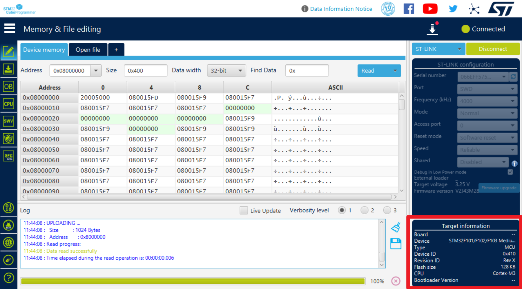
Download, install, and open STM32CubeProgrammer. Click "Connect" in the upper right corner to connect the debugger. After a successful connection, the target chip information will be displayed in the lower left corner.

Flash the widely circulated STLinkV2.J28.M18.bin firmware.

Note that this firmware version may not work properly and requires a firmware upgrade. Click "Disconnect" to disconnect the test board and the other debugger, leaving only this debugger connected.
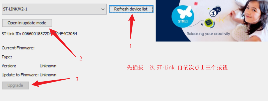
After plugging the debugger into the computer, without clicking any other buttons, directly click the "Firmware Upgrade" button
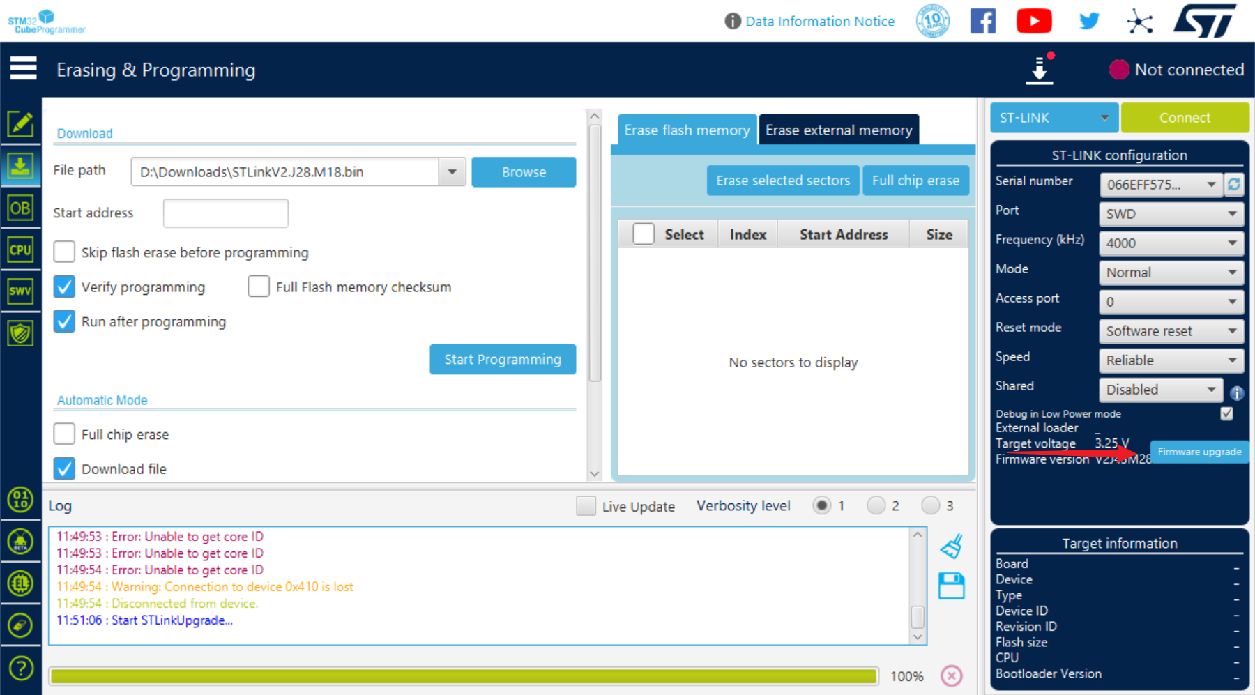
to upgrade the firmware and it will be usable normally.
After successfully flashing one debugger, you can use the male connector of this debugger to flash another debugger without needing to use the test board again.

The DAPLink board has a USB re-enumeration circuit, requiring DAPLink firmware compatible with ST-LINK/V2-1, such as DAP103
board thickness and 0.8 stacked 4-layer board, JLC04161H-3313 stacked board (1-4 layers of gold plating coupon can be used).
The Type-C DRP debugger can only act as a source, not a sink. If the target development board does not use a PD protocol chip, or if the PD protocol chip requires an external pull-down resistor, you can directly place the Rd resistor as designed in this article. If the PD chip has a built-in Rd resistor, it may be possible to achieve direction detection by connecting a pull-down resistor in parallel on one side of CC, but this has not been verified.
Conclusion:
No more padding.
Recommended
reading:
Ruan Xingzhi "DIY: Homemade DAPLink"
Arya Voronova "All About USB-C: Resistors And Emarkers"
Appendix
ST-LINK Indicator Light Meaning
The meanings of the two LEDs next to the STM32F103CBT6 are as follows:
Red flashing: Powered on, not connected to computer (most likely CH334 does not support crystal oscillator-free operation)
Solid red: Connected to computer, not connected to target chip
Red and green flashing alternately: Data transmission in progress
Green solid: Last data transmission successful
Red and green solid: Last data transmission failed
The LED next to the Type-C male port has the following meanings:
Not lit: Power supply is normal
Light lit: Power supply abnormal, possibly overcurrent or reverse flow
BOM
main component Taobao reference prices:
STM32F103CBT6: 2.2 yuan (free shipping)
CH334F / CH334P: 1.5 yuan (1 yuan shipping fee) (Note batch)
XC6206P332MR: 2 yuan (20 pieces, free shipping)
S9013: 2 yuan (100 pieces, free shipping
) TPS2553: 0.6 yuan (free shipping)
RS2227XUTQK10: 0.52 yuan (1 yuan shipping fee)
CH443K: 0.12 yuan (1 yuan shipping fee)
RS8901XF: Shipping fee: 0.45 yuan; 1 yuan shipping
fee; 16-pin Type-C surface mount female connector
: 2.8 yuan (10 pieces, free shipping); 24-pin Type-C male connector: 0.48 yuan; shipping fee: 1.5
yuan. The total cost of the main components for a single debugger is less than 10 yuan. According to the BOM exported from LCSC EDA, the price of five LCSC surface mount boards with all components is approximately 140 yuan.
More pictures.


STLinkV2.J28.M18.bin
DAP103-dapboot-combined-stlink.bin
PDF_Type-C SWD VCP USB One-Line ST-LINK.zip
Altium_Type-C SWD VCP USB One-Cable ST-LINK.zip
PADS_Type-C SWD VCP USB One-Cable ST-LINK.zip
BOM_Type-C SWD VCP USB One-Cable ST-LINK.xlsx
92519
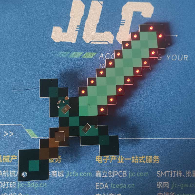
Replica of Minecraft Greatsword - Solar Powered and Supercapacitor Version
I modified the Minecraft Greatsword a bit. The original required a battery, which was very inconvenient, so I replaced it with a supercapacitor, eliminating the need for a charging circuit. I also added a solar charging panel, so even when the battery is dead, I can enjoy playing again by letting it dry in the sun!
I modified the Minecraft Greatsword a bit. The original required a battery, which was very inconvenient, so I replaced it with a supercapacitor, eliminating the need for a charging circuit. I also added a solar panel, so even when the battery is dead, I can enjoy playing again by letting it dry in the sun!
Original: https://oshwhub.com/ftp_li/wo-de-shi-jie-tie-jian


studio_video_1725016404596.mp4
PDF_Minecraft Greatsword Replica - Solar Energy and Supercapacitor Version.zip
Altium_Minecraft Greatsword Replica - Solar and Supercapacitor Version.zip
PADS_Minecraft Greatsword Replica - Solar and Supercapacitor Version.zip
BOM_Minecraft Greatsword Replica - Solar and Supercapacitor Version.xlsx
92520
Simple microcontroller power supply module
This design addresses the common problem of needing to provide a 3.3V high level to an STM32 microcontroller when only a power bank is readily available. The circuit is simple and inexpensive.
Update Log
2024.8.30 — First Release of Open Source Project
---------------------------------------------------------------------------------------------------------------------------------------------------------------------
Project Description:
When debugging STM32 code, sometimes it's necessary to provide a high-level voltage to the microcontroller for testing. However, since I don't have a dedicated power supply on hand, only a power bank that can provide 5V, debugging is quite troublesome. Recently, I learned about the AMS1117 LDO chip, so I drew a simple module to solve this problem.
The circuit schematic references some AMS1117 modules from open-source platforms and is also based on the datasheet.
---------------------------------------------------------------------------------------------------------------------------------------------------------------------
Project Introduction:
Power is supplied via Type-C, outputting 5V, 3.3V, and GND through a single row of bent pins. DuPont wires can be used to connect to the required locations.
---------------------------------------------------------------------------------------------------------------------------------------------------------------------
Circuit Schematic
1. Power Input Section:
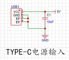
Since there is no data transmission requirement, a 2-pin Type-C direct-plug interface was chosen for easy soldering and a simple circuit.
2. The AMS1117 LDO circuit
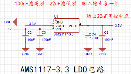
has two capacitors connected to both the input and output: one to filter high frequencies and the other to filter low frequencies. According to the datasheet, a 22uF tantalum capacitor is required at the output. The datasheet specifies this as follows:
3. The power indicator circuit is

a simple LED circuit using a 1kΩ resistor. However, in actual use, the brightness was found to be somewhat excessive. Trying a 5kΩ or 10kΩ resistor might yield a more suitable brightness.
4. The output interface

is a single-row bent-pin output interface, connected using DuPont wires.
---------------------------------------------------------------------------------------------------------------------------------------------------------------------
The PCB traces
use filled areas to connect the input and output, allowing for a larger current flow, as shown in the figure:

---------------------------------------------------------------------------------------------------------------------------------------------------------------------
Components and Costs
AMS1117-3.3 —— 0.42 yuan
22uF tantalum capacitor —— 0.47 yuan
Adding other resistors and capacitors, the cost is approximately 1.5 yuan
---------------------------------------------------------------------------------------------------------------------------------------------------------------------
Attached
is the AMS1117 datasheet (from LCSC Mall)
---------------------------------------------------------------------------------------------------------------------------------------------------------------------
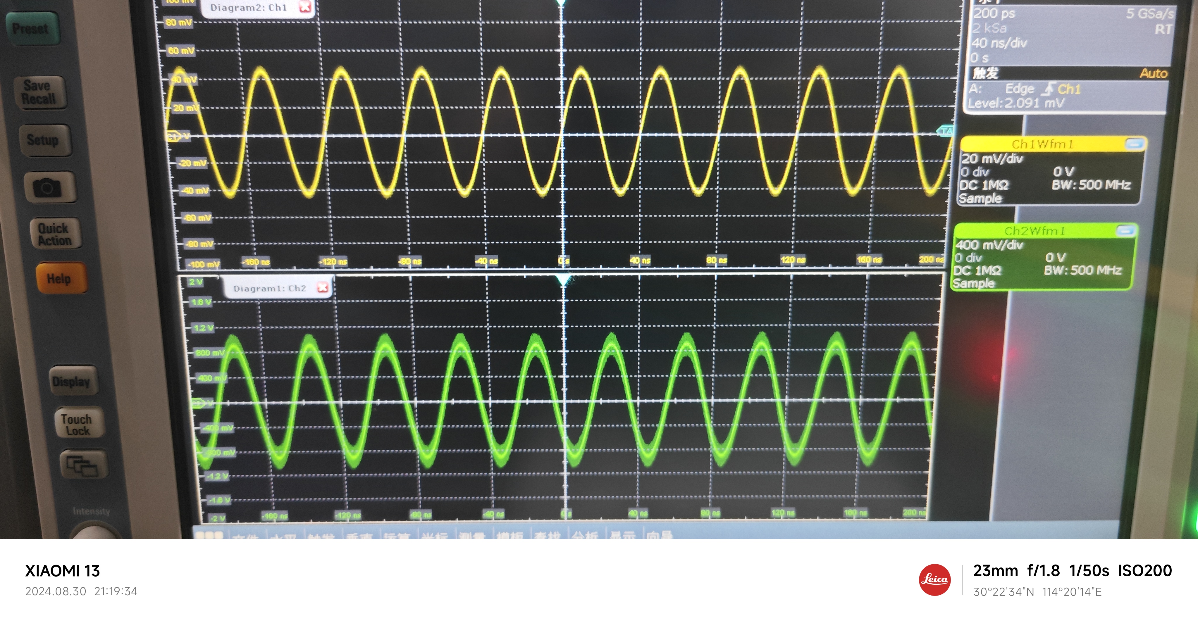
Performance Demonstration
5V Output:

3.3V Output:
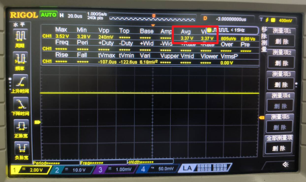
3.3V Output Ripple:
The ripple is approximately 1.14mV

---------------------------------------------------------------------------------------------------------------------------------------------------------------------
Finally
, because short-circuit protection is not implemented, and the 5V output is directly led from the input, shorting it to GND may cause power banks and other power supplies to malfunction. When using it, be sure to ensure that the 5V and 3.3V outputs are not shorted to GND!
Wishing everyone a successful completion! Safe use!
AMS1117.pdf
PDF_Simple Microcontroller Power Supply Module.zip
Altium Simple Microcontroller Power Supply Module.zip
PADS Simple Microcontroller Power Supply Module.zip
BOM_Simple Microcontroller Power Supply Module.xlsx
92521
STM32F103VET6 core board
STM32F103VET6 core board
1. Copyright Notice:
This project is an original work by m4um4um4u. Please indicate the source when reprinting.
2. Project Introduction:
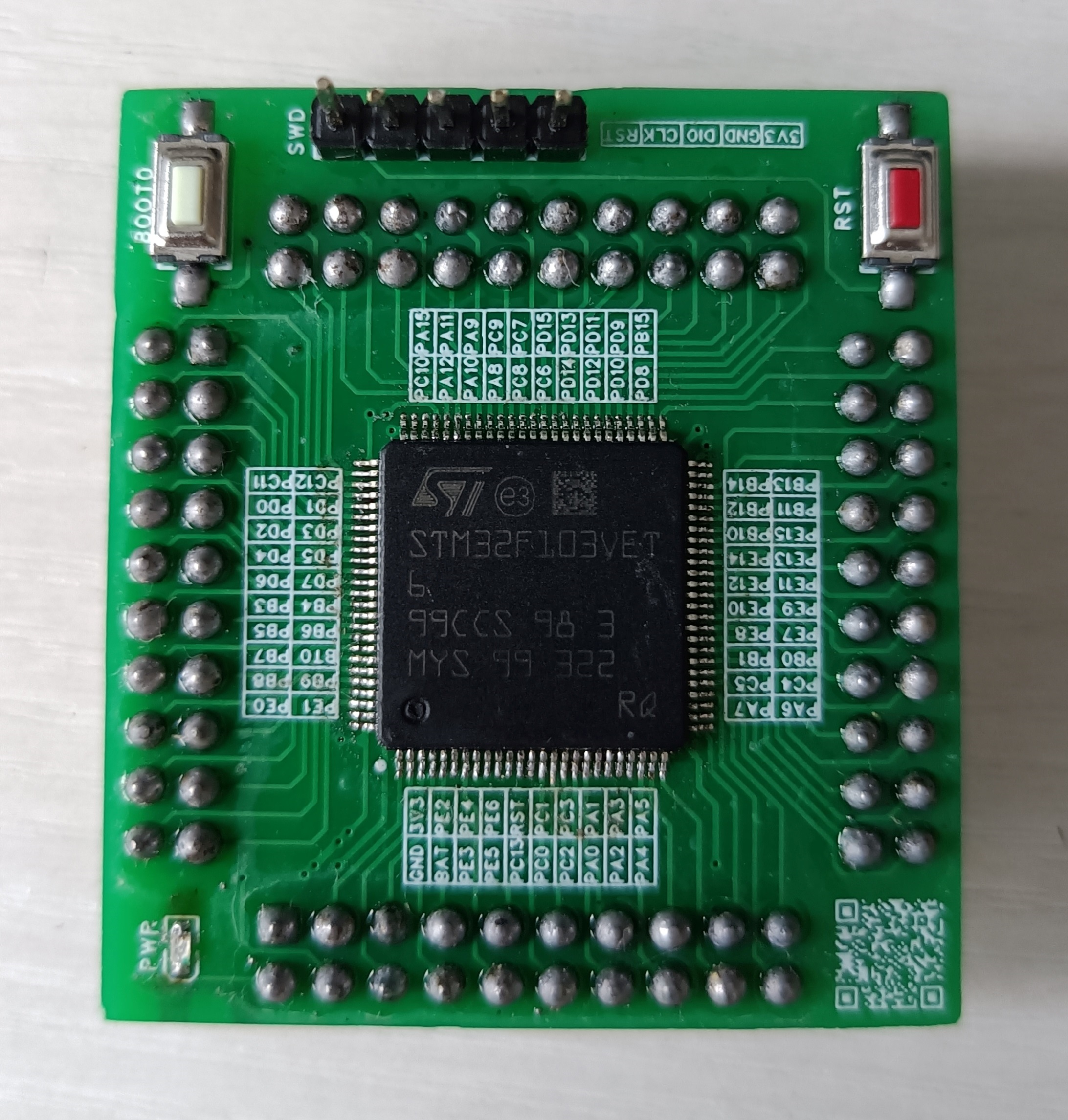
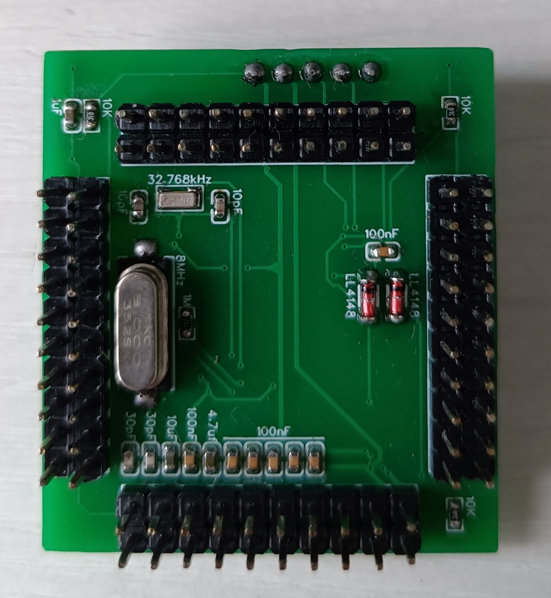
This project is an STM32F103VET6 core board with a width of 43.688mm and a height of 39.497mm. The core board features an SWD download interface, an 8MHz main crystal oscillator, a 32.768kHz clock crystal oscillator, a VBAT pin (which can be used to connect a backup battery to power the RTC and backup registers, ensuring continuous timing for the RTC and saving sensitive data; VBAT can be omitted for functions not used), a BOOT0 button (BOOT0 is high when pressed), and an RST button. The BOOT0 and RST pins are separately brought out (providing greater development flexibility). VREF is connected in parallel with the chip power supply (the chip power supply voltage should be 3.3V). The pin spacing is 2.54mm (for easy connection of other devices using DuPont wires).
3. Physical Diagram
PDF_STM32F103VET6 core board.zip
Altium_STM32F103VET6 core board.zip
PADS_STM32F103VET6 core board.zip
BOM_STM32F103VET6 Core Board.xlsx
92522
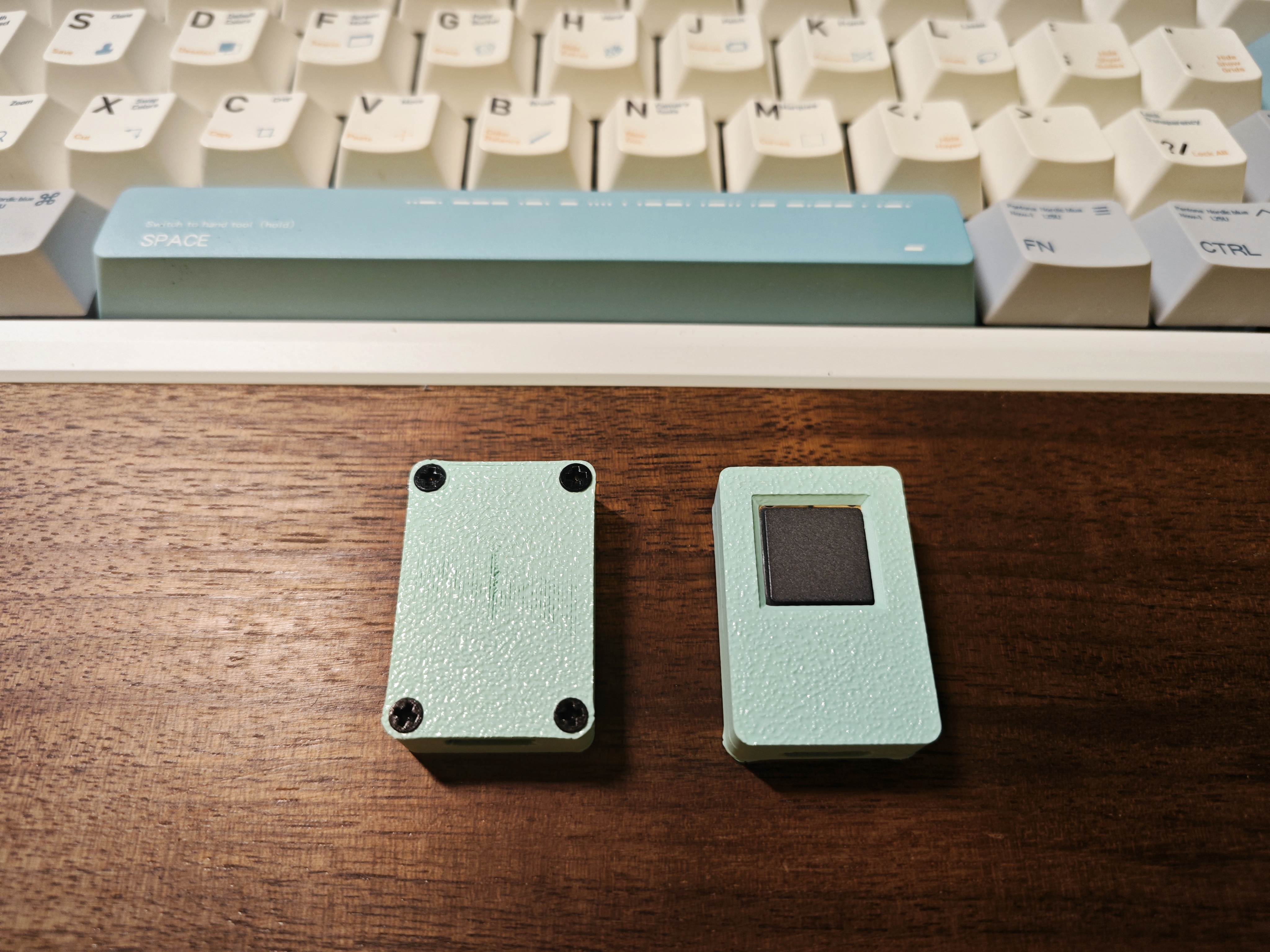
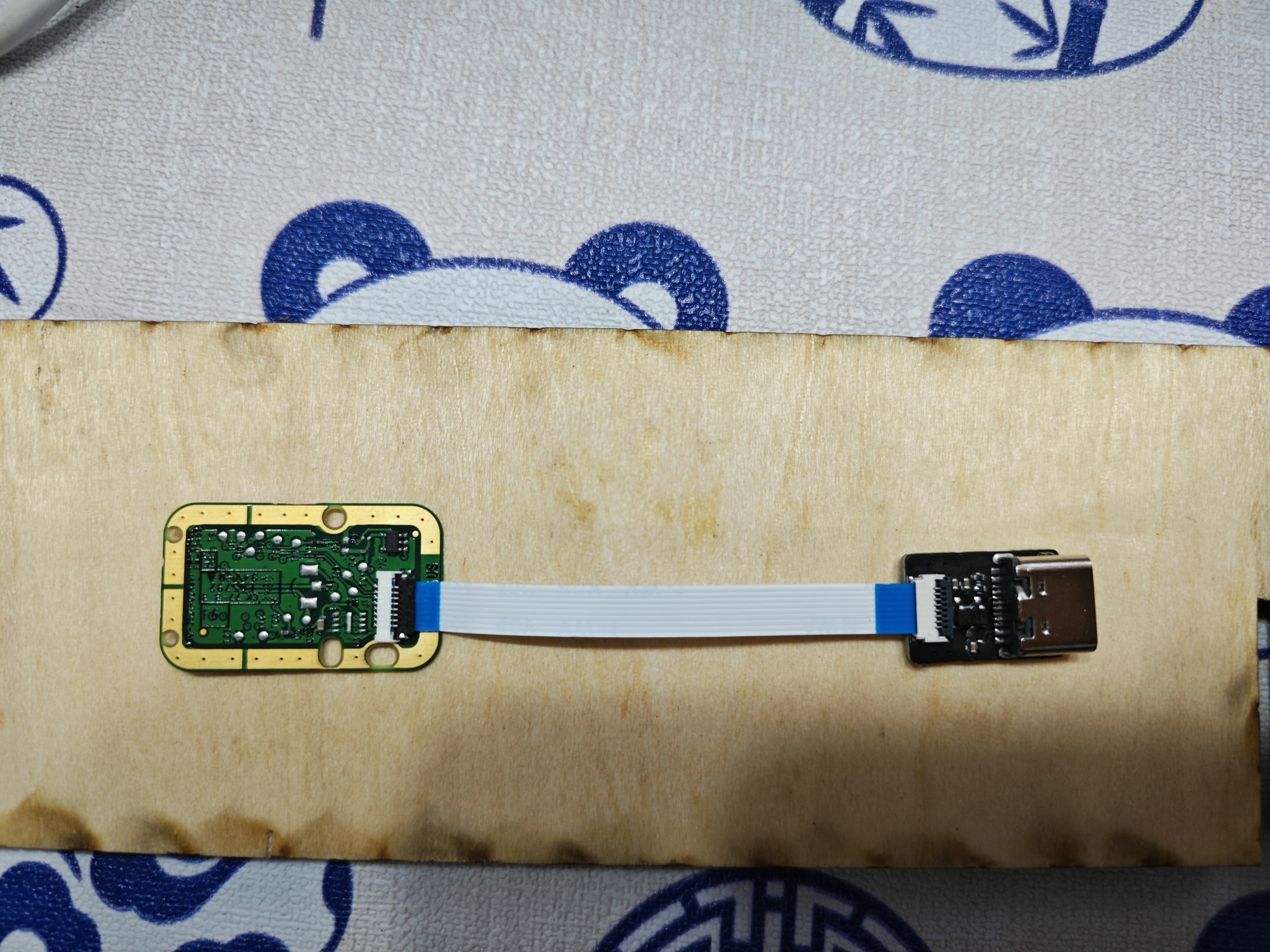
Windows Hello fingerprint module
Fingerprint recognition module USB adapter board
This adapter board modifies the LDO of this module and replaces it with a more solderable enclosure
for mounting the fingerprint module. The module is a Synaptics fingerprint module. The enclosure is available at: [open source address missing].
Accessories include: M2*4, countersunk screws*4,
FPC 0.5mm 8-pin 5cm Type A.

PDF_WindowsHello fingerprint module.zip
Altium_WindowsHello fingerprint module.zip
PADS_WindowsHello fingerprint module.zip
BOM_WindowsHello fingerprint module.xlsx
92523
Bluetooth to MQTT gateway
This project can forward Bluetooth device data to an MQTT server and remotely control Bluetooth devices via the MQTT server.
IOT-Router Bluetooth to MQTT Gateway


This is a C-language IOT-Router
program source code: https://github.com/JasonYANG170/IOT-Router
Features
✅ Supports connecting Bluetooth devices to an MQTT server
✅ Supports remote control of Bluetooth devices via MQTT
✅ Supports local Web server control of Bluetooth devices
✅ Supports ETH Ethernet connection
✅ Supports serial port debugging
✅ Theoretically supports Ethernet to WIFI network conversion, acting as a router
If you encounter any problems, please raise issues with me
Project Parameters
This design uses an ESP32C3 main controller to achieve lower costs;
this design uses a W5500 to achieve Ethernet access;
this design uses an AHT10 to achieve environmental data monitoring;
Open Source License
This project follows the CC BY-NC-SA 4.0 open source license. When using this program, please indicate the source and provide a copyright statement.
This project is for learning and research purposes only. Unauthorized commercial profit is strictly prohibited.
If you have better suggestions, PR is welcome. If you
like this project, please give me a Star ⭐

Physical Pictures
1
2


PDF_Bluetooth to MQTT Gateway.zip
Altium_Bluetooth to MQTT gateway.zip
PADS_Bluetooth to MQTT Gateway.zip
BOM_Bluetooth to MQTT Gateway.xlsx
92524
Broadband VGA and control board
Wideband VGA variable gain amplifier module, with bandwidth up to 3.8G and gain range from -62dB to 40dB.
This module is a cascaded HMC472 + HMC589, offering high-precision gain control with a gain/loss step of 0.5dB, capable of handling the amplification or loss requirements of most signal processing problems in electronics design competitions.
I personally used it in Problem C of the 2024 electronics design competition, and it worked exceptionally well in practice.
PDF_Broadband VGA and Control Board.zip
Altium_Broadband VGA and Control Board.zip
PADS_Broadband VGA and Control Board.zip
BOM_Broadband VGA and Control Board.xlsx
92525
Allwinner H3
I bought the H3 using Xianyu (a second-hand marketplace app), it's the one with the cloud storage box.
Ideal for those wanting to learn Linux at a low cost.
The firmware is too large to upload here; join the group (757578508) to get it.
Ubuntu and Debian are available.
Note: After removing the core, apply a ring of low-temperature solder before using a heating pad to remove it; otherwise, the solder pads may come off.
Core board link:
[Xianyu link](https://m.tb.cn/h.gmuzAYJ?tk=4F4k3fUbgCF ZH4920) "Come grab a bargain! [Brand new Allwinner H3 development board, chip included, well-packaged, suitable for learning, includes casing and power supply]"
(Click the link to open directly)
Project Introduction:
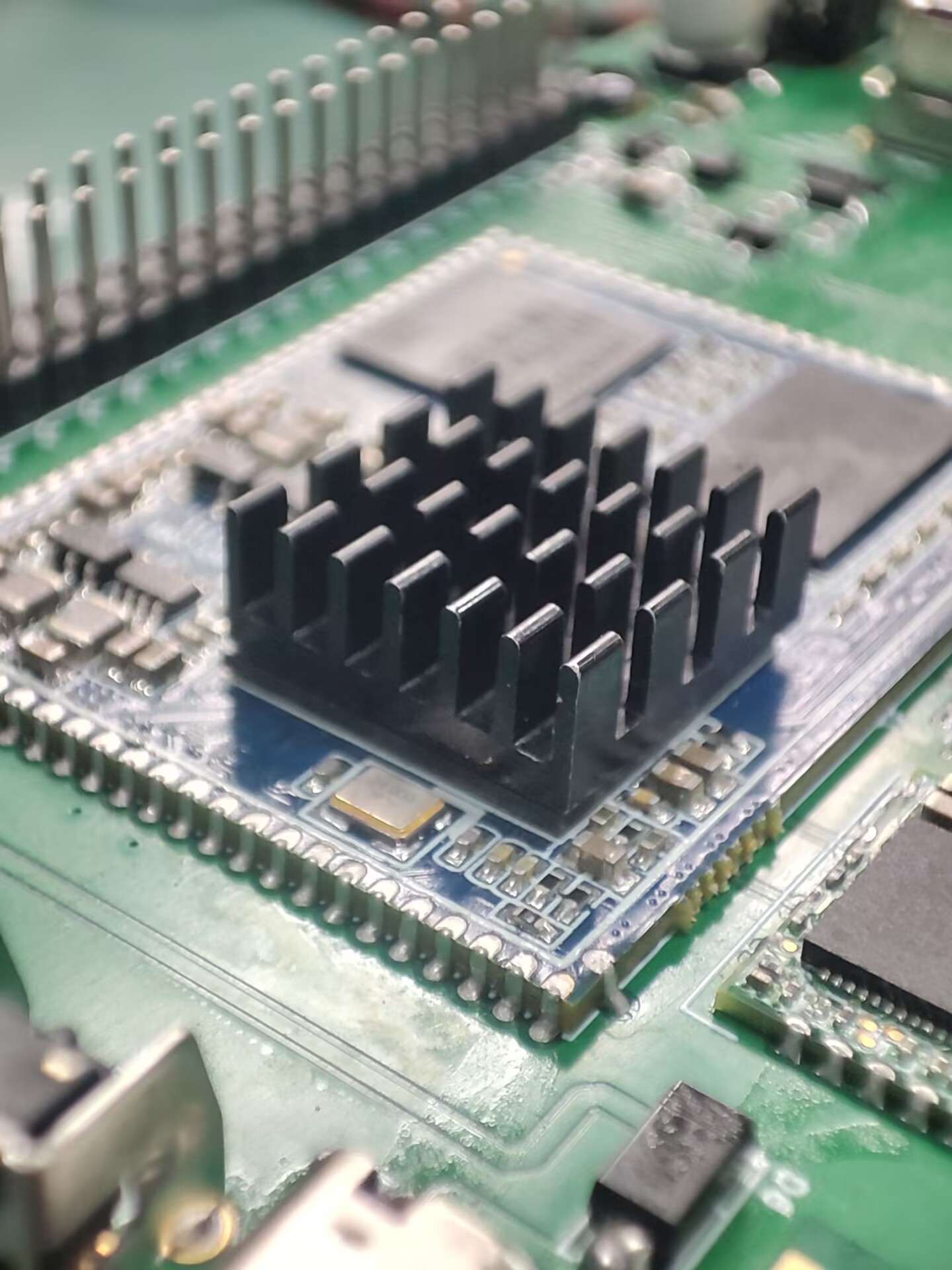
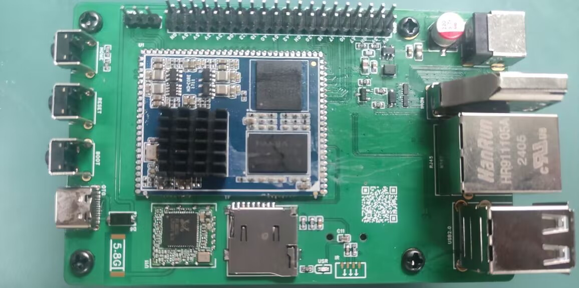
This project was inspired by an Allwinner H3 core board I found on Xianyu (a second-hand marketplace). I designed it as a baseboard, and all basic functions have been tested and are working normally.
The project
features several GPIO and serial ports. I also added a spare Wi-Fi module. Antennas can be found on Taobao, although they don't need to be soldered.
Project Parameters:
Storage is 256MB + 4GB, priced at 20 RMB including a charger, which is a great deal.
Principle Analysis (Hardware Description):
The schematic diagram of the core board is from the official website. I replaced some components and laid out the layout myself.
The software code
is the official firmware, and it works quite well.

1. Firmware Burning Tutorial: First, burn the firmware to the SD card
. 2. Log in as root user. Do not log in first and then su root (I've already encountered this problem).
3. Execute in the terminal: nand-sata-install
4. Select 2 Boot from eMMC - system on eMMC
5. A prompt will pop up asking to erase the data on the eMMC. Select Yes
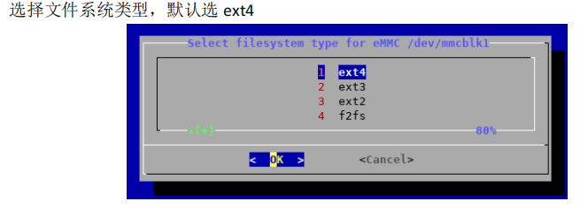
6. Select the file system type. The default is ext4.
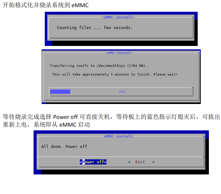
7. Begin formatting and burning the system to eMMC.
8. Wait for burning to complete. Select "Power off" to shut down the device. After the blue indicator light on the board goes out, you can remove the TF card and power on again. The system will then boot from eMMC.
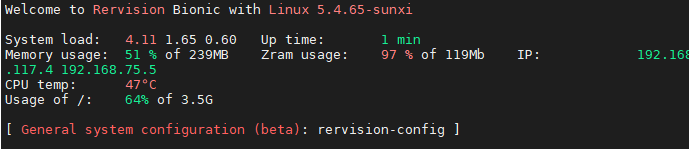
WiFi should boot normally and IP address should be obtained correctly.

Note:
Network port should be normal,
USB port should be normal,
serial port should be normal,
WiFi should be normal,
debug should be present, silkscreen printing is not applied.
PDF_Allwinner H3.zip
Altium_AllwinnerH3.zip
PADS_AllwinnerH3.zip
BOM_AllwinnerH3.xlsx
92526
USB 2.0 expansion dock (3*USB + 2*UART + 1*STlink)
Originally, I was using a regular docking station for debugging, which had two serial debuggers and an ST-Link connected to it. However, it looked messy, and it seemed that there weren't any products on the market that combined two serial ports and an ST-Link. So, I created this USB docking station.
First, I would like to thank engineer Chen Zhe for his STlink open-source project:
https://oshwhub.com/CYIIOT/ST_LINK-V2_1.
This project uses two ICs:
1. FE2.1 (USB 1-to-7 expansion chip)
2. STM32F103CBT6 (I personally tested that the C8T6's memory is too small, and the firmware cannot be burned).
The functions are as follows:
1. Two * USB 2.0 + USB 2.54 interfaces (used for direct USB debugging with DuPont wires)
2. Two * UARTs (sometimes two serial ports are used to control two microcontrollers respectively)
3. STlink programming interface (only SWDIO and SWCLK)
. All components are surface-mount components. This allows for a direct setup using a heating platform, and also provides stability and a more comfortable viewing experience when placed on a table.
The pin order for burning firmware from top to bottom is (3V3, SWCLK, SWDIO, GND).
STLinkV2.J28.M18_Firmware.zip
PDF_USB2.0 Expansion Dock (3 USB + 2 UART + 1 STlink).zip
Altium USB 2.0 Dock (3 USB + 2 UART + 1 STlink).zip
PADS_USB2.0 Dock (3 USB + 2 UART + 1 STlink).zip
BOM_USB2.0 Dock (3 USB + 2 UART + 1 STlink).xlsx
92527
Linear magnetic axis keyboard - Hanmei
The fragrance of plum blossoms comes from the bitter cold, hence the name "Winter Plum" (寒梅). This is a simplified version of a linear magnetic axis keyboard designed using an IC in an LQFP32 package.
The name "Hanmei" (寒梅, meaning "Winter Plum") comes from the Chinese proverb "The fragrance of plum blossoms comes from the bitter cold." This is a low-cost linear magnetic keyboard designed using the AT32F425K8T7 microcontroller in an LQFP32 package, paired with a low-cost linear Hall effect sensor 49E. The design precision is 0.5mm. The schematic is a 6x18 matrix (actual maximum 6x15), which can be modified to layouts of 98 keys or less (maximum 108 keys; making a 104-key layout requires moving many unused keys, which is cumbersome; layouts of 98 keys or less are only recommended). A 61-key binary firmware is also provided for DIY projects.
The communication protocol is a custom OpenAgreementHID (OHID) protocol, which will be updated periodically. The attached OHID protocol document can be used to write your own host computer.
Note: The prototype uses a front-mounted iridescent package; you can modify it to a reverse-mounted package.
Technical exchange group:

OpenAgreementHID_0603.pdf
PDF_Linear Magnetic Axis Keyboard - Hanmei.zip
Altium Linear Magnetic Axis Keyboard - Hanmei.zip
PADS Linear Magnetic Axis Keyboard - Hanmei.zip
BOM_Linear Magnet Keyboard - Hanmei.xlsx
92528
electronic


 京公网安备 11010802033920号

 FU-68PDF-510M93B


