 is divided into a main power supply section,
 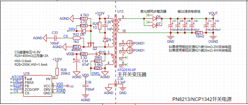 a digital feedback section, isolated power supply, and
  a host computer communication section with safety isolation.
  Working Principle:
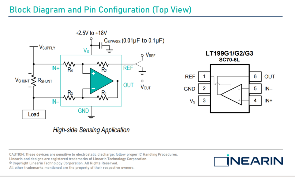
 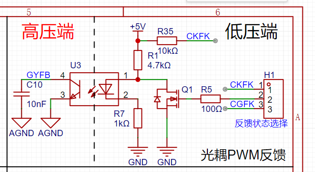 Current sampling uses the LT199G1, modified from the original official circuit to low-side detection, making it suitable for current detection at higher voltages. The voltage signal across the sampling resistor is amplified by the LT199G1 and then input to the STC8G-ADC pin. The output of the LT199G1 is clamped by a Zener diode to prevent the output voltage signal from being too high and damaging the MCU.
 By switching the feedback type, it can also be used as a regular adjustable output voltage switching power supply.
 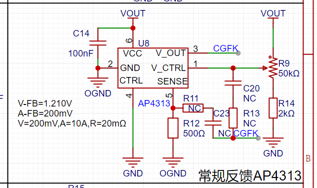 Software instructions:
  The host computer uses LabVIEW 2018 to write
 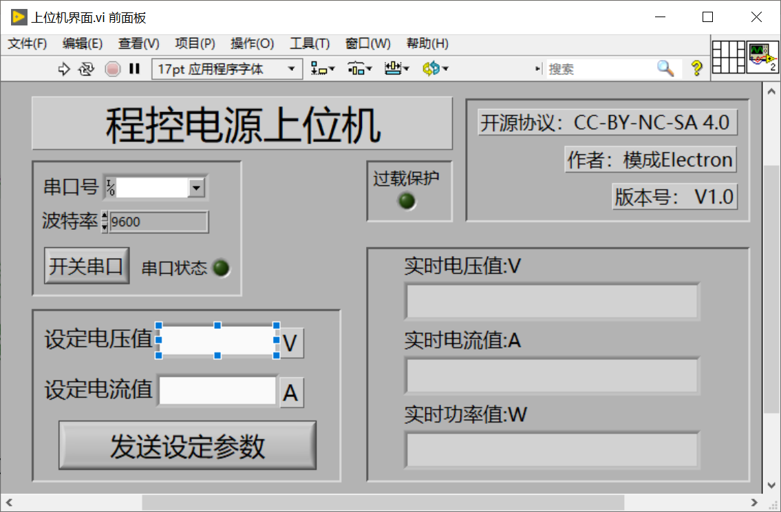 the communication baud rate, which needs to be changed to 115200bit before startup.
 Design considerations:
 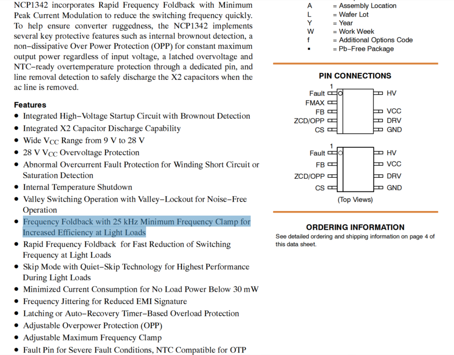 Soldering the power transistor will cause both the power transistor and NCP1342 to break down. During the overall testing, it operated stably once, but after restarting, both the power transistor and NCP1342 exploded.
All reference designs on this site are sourced from major semiconductor manufacturers or collected online for learning and research. The copyright belongs to the semiconductor manufacturer or the original author. If you believe that the reference design of this site infringes upon your relevant rights and interests, please send us a rights notice. As a neutral platform service provider, we will take measures to delete the relevant content in accordance with relevant laws after receiving the relevant notice from the rights holder. Please send relevant notifications to email: bbs_service@eeworld.com.cn.
It is your responsibility to test the circuit yourself and determine its suitability for you. EEWorld will not be liable for direct, indirect, special, incidental, consequential or punitive damages arising from any cause or anything connected to any reference design used.
Supported by EEWorld Datasheet
EEWorld
subscription
account

EEWorld
service
account

Automotive
development
community

Robot
development
community

About Us Customer Service Contact Information Datasheet Sitemap LatestNews


Room 1530, 15th Floor, Building B,
No.18 Zhongguancun Street,
Haidian District,
Beijing, Postal Code: 100190
China
Telephone: 008610 8235 0740
 京公网安备 11010802033920号

 805-004-03MT19-3PA


