I. Project Background: This project
involves learning the CW32 microcontroller and ADC (Analog-to-Digital Converter) circuits to implement a current and voltage meter.
II. Hardware Design
: 1. Schematic Diagram

2. Circuit Analysis
1. Power Supply Circuit:
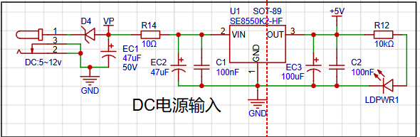
LDO (Low Dropout Linear Regulator) Selection:
This project uses an LDO as the power supply. Considering that most voltmeter products are used in industrial scenarios with 24V or 36V power supplies, the SE8550K2, with a maximum input voltage of 40V, was selected. The main reason for not using a DC-DC step-down circuit to handle the large voltage drop is to avoid introducing ripple interference from the DC-DC circuit during the design process. A secondary reason is to reduce project costs.
The Role of the Series Small Resistor (10Ω):
This project additionally uses a series small resistor (10Ω) for voltage division. On the one hand, this reduces the problem of severe heat generation caused by the large voltage drop of the LDO under high voltage conditions. On the other hand, it utilizes the principle that the series 10-ohm low-power resistor has low overcurrent, acting as a low-resistance fuse, providing overcurrent protection or short-circuit protection. (The point about using a resistor as a fuse is that, because the resistor is in an overcurrent state and heating up, it is 99% likely to be an open circuit, and it will almost never short-circuit. Its fault analysis determines that it will primarily be an open circuit, meaning it will burn out rather than short-circuit.) The
small series resistor (10Ω) can also reduce the peak value of the power-on surge, preventing damage to the LDO from excessive surges.
If electrolytic capacitors are not used, the small series resistor (10Ω) can also prevent the inductance of the wires and the ceramic capacitor from resonating during hot-plugging. Because ceramic capacitors have very low ESR, the damping in the LC network is very low, and the gain at the resonant point will be very high. Adding an external resistor to provide damping can suppress the gain at the resonant point.
Circuit design points and specifications
: When drawing power supply circuits, whether schematics or PCBs, the following points should be noted:
Schematic specifications: GND should be facing down, power supply should be facing up, and ground should not be facing up.
Capacitor design: Regardless of the schematic or PCB, electrolytic capacitors should be placed first, followed by ceramic capacitors.
Grounding design: Single-point grounding. The ground of the current power supply is connected to the GND of the main electrolytic capacitor of the current power supply. The ground of the main electrolytic capacitors of each stage power supply is connected to the GND of the main electrolytic capacitor of the previous stage power supply.
2. MCU Selection Analysis
To reduce learning costs, this project uses the LCSC CW32F030C8T6 development board (core board) as the main controller. Downloadable materials can be found on the LCSC development board website.
Key advantages of the CW32 in this project
: Wide operating temperature range: -40~105℃;
Wide operating voltage range: 1.65V~5.5V (STM32 only supports 3.3V systems)
; Strong anti-interference: HBM ESD 8KV; All ESD reliability reaches the highest international standard level (STM32 ESD 2KV)
; Project focus - Better ADC: 12-bit high-speed ADC, achieving ±1.0LSB INL 11.3ENOB; Multiple Vref reference voltages... (STM32 only supports VDD=Vref);
Stable and reliable eFLASH technology. (Flash0 waiting)
3. Voltage sampling circuit The voltage
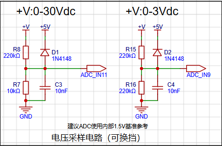
divider resistor in this project is designed to be 220K+10K, so the voltage division ratio is 22:1 (ADC_IN11).
The voltage divider resistor is
selected to measure the maximum voltage. For safety reasons, this project uses 30V (the actual maximum can be displayed as 99.9V or 100V).
The ADC reference voltage is 1.5V in this project, and this reference voltage can be configured through the program.
To reduce the power consumption of the sampling circuit, the low-side resistor (R7) is usually chosen as 10K based on experience.
Then, the high-side resistance of the voltage divider resistor can be calculated using the above parameters.
The required voltage division ratio is calculated, i.e., the ADC reference voltage. The input voltage is designed; using known parameters, 1.5V/30V = 0.05 can be calculated.
The high-side resistance is calculated as the low-side resistance/voltage division ratio; using known parameters, 10K/0.05 = 200K can be calculated.
A standard resistor is selected: a resistor slightly higher than the calculated value of 200K is chosen. We usually choose E24 series resistors; therefore, in this project, 220K, which is greater than 200K and closest to the calculated value, is selected.
If, in actual use, the voltage to be measured is lower than 2/3 of the module's design voltage (66V), the voltage divider resistor can be replaced and the program modified to improve measurement accuracy. The following example illustrates this:
Assuming the measured voltage is no higher than 24V and other parameters remain unchanged,
calculations show 1.5V/24V = 0.0625, 10K/0.0625 = 160K. 160K is a standard E24 resistor and can be directly selected, or a higher value 180K can be chosen with some redundancy.
If, in actual use, the voltage to be measured is higher than the module's 99V design voltage, a different resistor can be selected. To achieve a wider voltage measurement range, one can choose to replace the voltage divider resistor or modify the reference voltage. The following example illustrates this:
Assuming the measured voltage is 160V, the solution is to increase the voltage reference to expand the range.
Given that the voltage division ratio of the selected resistor is 0.0145, we can calculate 160V * 0.0145 = 2.32V using the formula. Therefore, we can choose a 2.5V voltage reference to achieve the increased range (increasing the range will reduce accuracy).
Considering the potential fluctuations in the measured power supply, a 10nF filter capacitor is connected in parallel with the low-side voltage divider resistor to improve measurement stability.
5. Digital Tube Driver:

This project uses two 0.28-inch three-digit common-cathode digital tubes as display devices. Compared to displays, digital tubes have better visibility in complex environments. Depending on the actual usage environment, smaller current-limiting resistors can be used to achieve higher brightness. Furthermore, digital tubes have better mechanical properties and are not as easily damaged by external forces as displays. They are widely used in industrial and other applications requiring stable and reliable operation. From a development learning perspective, this makes it easier to learn electronic measurement principles and related development more purposefully.
In this project, after actual testing, configuring the current-limiting resistors (R1~R6) of the digital tubes to 300Ω resulted in good visibility for both red and blue digital tubes, with a soft and non-glaring brightness.
Strictly speaking, the current-limiting resistors should be added to the segments; adding them to the digits would affect the display effect. In our actual design, we added them to the digits to save a few resistors, but the impact on the display was not significant. Therefore, we added them to the digits for convenience.


 京公网安备 11010802033920号

 1.5KE18H36


