Motion sensor circuit diagram, build a simple automatic motion sensor light circuit
Source: InternetPublisher:桂花蒸 Keywords: Circuit Analysis Motion Sensor PIR Updated: 2025/03/04
This is a simple automatic motion sensor light circuit. When we use battery-powered lighting for a long time, even using LED bulbs that consume very little power will consume most of the battery power. So, is there a way to save as much power as possible?
In some places where LED lights are installed, it is not necessary to turn on the lights all night. For example, in front of the bathroom, corridor or other places. In these places, we can install a switch to turn them on or off when needed.
But wouldn't it be better if, for example, the light turned on by itself when people walked by, stayed on for about 5 minutes, and then turned off by itself?
If the person walks back during these 5 minutes (for example, during the third minute), the system will start another 5-minute timer. Therefore, the total time the LED remains on is 3+5 = 8 minutes.
Or make it clearer to you.
I usually leave a 12V 3W LED on overnight, or about 10 hours. The LED requires 3W/12V = 0.25A per hour
. 5.10A total for 2 hours, so we need to use at least a 2.5Ah battery.
However, if we only use the light for one hour each night, the current we need will be 25% (2.5A) of the normal 10.0A required, leaving 90% of the surplus energy.
When we use this circuit, we will only need to use the light for less than an hour every night. It will help us save a lot of energy.
How it works
This circuit is similar to the motion detector alarm circuit. We just replace the main component 12V siren with 12V LED bulb and its block diagram is shown below.
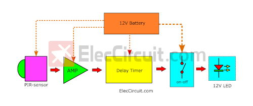
Block diagram of the automatic motion sensor light circuit
Each block can be divided into:
12V battery as power source.
Same PIR motion sensor as before.
Same amplifier circuit.
New Delay Timer, because the time delay of PIR motion sensor cannot exceed 200 seconds. Therefore, we need to add an additional circuit to increase the delay to 5 minutes or 300 seconds
Better switch controller: We chose MOSFET instead of relay because of its better current efficiency.
New delay timer circuit
The principle of the timer circuit we are used to is to use a capacitor to hold the voltage at the load or output terminal, and then gradually and continuously release the voltage until it is exhausted.
Let's start with something we already know: amplifier circuits.
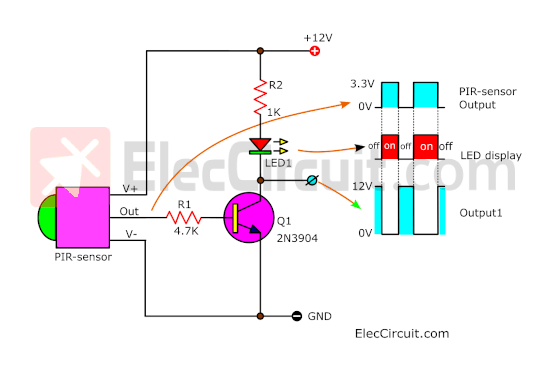
Simple common emitter NPN transistor amplifier circuit
The block diagrams below show two ways we can make a timer; we can use them as ideas for timer circuit design.
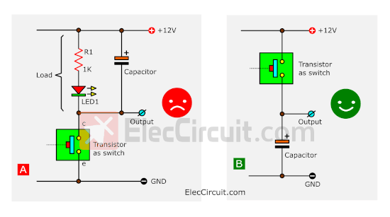
Comparison of different timer concepts
In this case, the transistor will act as a switch. The left diagram (A) shows a capacitor connected in parallel to the load, which prevents the voltage from disappearing like in the timer circuit.
Therefore, what we should do is change the position of the switch and capacitor to the position shown in the right figure (B). When the switch is turned on, the current will charge into the capacitor, and when the switch is turned off, the current in the capacitor will discharge, which is the principle of the timer circuit.
But since this is a common emitter transistor amplifier circuit, the position of the NPN transistor as a switch does not match the correct image (B).
We also do not want to change the amplifier circuit. Therefore, we need to change its layout to the one shown in the following circuit.

Timer concept by adding a PNP transistor switch
The additional circuit is a common emitter amplifier circuit which uses a PNP transistor instead.
It conducts current only when Q1 is turned on or CE becomes a closed circuit. The base of the PNP transistor thus receives a forward bias, causing it to conduct current.
Therefore, let the high current from the 12V battery flow through its E to C and charge the capacitor through the diode. In addition, the voltage level of output 2 will increase by nearly
12V, and it can maintain this voltage level for about 5 minutes or so even after the input signal has disappeared.
We put the diode there to protect the voltage from the capacitor from flowing back into the PNP transistor.
Learning through signal graphs
We want you to understand it thoroughly. So, refer to the signal diagram below and compare point P, output 1, point D, and output 2.
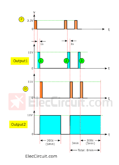
Compare point P, output 1, point D and output 2
When we walk past the PIR sensor, there will be a 3.3V pulse signal at point P. Then, about 1 second later, the state of this signal will change from high to low.
Output 1 will then send out its first pulse signal with the same time span as point P, about 1 second, but with a higher voltage of about
11 V. When this signal starts to decrease, point D will also pulse in the same way.
The current at point D will flow through the diode to charge the capacitor, resulting in output 2 also having the same voltage level of 11V.
After 1 second, the pulse signal state at point D will change from high to low, but at output 2, the voltage level will remain at
5V for the next 11 seconds or about 300 minutes. Then it returns to low as usual because the capacitor is discharged.
Then, when we walk past the PIR sensor again, it will send out the same signal again. At Output 1, there will be a second pulse signal lasting 1 second. At point D, there will be a pulse signal with enough voltage to charge the capacitor again. The voltage level of Output 2 will remain at 11V as before, even though we have passed by.
However, if we walk past the PIR sensor again in the third minute, the process should be the same as before. When the third pulse signal is at output 1 and the pulse signal is at point D again, there will be a current to charge the capacitor and discharge it again, making the total time of output 2 8 minutes.
With these ideas as a foundation, let's try to use them to create a simple timer circuit.
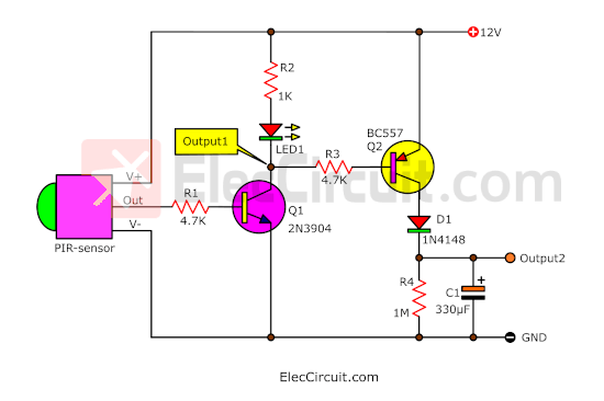
The simple timer circuit with the PIR motion sensor works great! We added R4 to adjust the time constant to what we wanted, which was about 5 minutes. As for R3, it helps reduce the base current of Q2 in the same way as the other transistor circuits.
But currently, the current output of output 2 is still too low to drive a load or a 12V 3W LED. It needs about 0.5A or more.
There are many ways we can handle this; usually, we would choose a relay to turn the load on and off. This is easy, but there must always be a little current flowing through the relay coil, about 30mA or more.
Therefore, we chose a MOSFET instead of a relay because it is low noise, has no moving mechanisms, and is more suitable for use as a switch than a transistor. For this exact IRF540, it can handle about 33A of current and about 100V of voltage.
In the circuit below, we put all the components together to turn it into a complete automatic motion sensor light circuit.
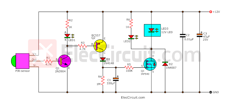
Complete Automatic Motion Sensor Light Circuit
LED2 indicates that the load is working.
C2 and C3 help reduce unwanted signal noise that could cause circuit malfunction.
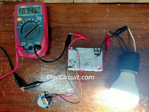
Build this circuit
My daughter first tested the circuit on a breadboard to see if it worked properly.
After seeing that it works fine, the next step is to assemble it into a solderable breadboard PCB
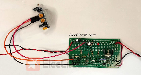
We have been using it for a few months now and it has been working great so far.
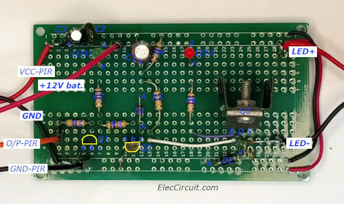
Component layout for solderable breadboard PCB
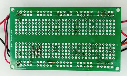
Solderable breadboard PCB bottom
NOTE: We should adjust the delay time on the PIR motion sensor to the minimum value.
in conclusion
This circuit helps a lot in saving battery energy as we don't have to keep the light on all night. It also helps in extending the life of the bulb.
- What is FPGA
- How do I choose the gain of an operational amplifier?
- Analysis of Operational Amplifier Differentiator Circuit
- Advantages and Disadvantages of Negative Feedback Circuits, Analysis of Operational Amplifier Feedback Circuits
- LM337 pin diagram and parameters, LM337 application circuit diagram
- An article explains the working principle of the Wheatstone bridge
- Symbol/working principle/type/characteristics/application scenarios of depletion-mode MOSFET
- How does a series arrangement of Zener diodes affect the electrical behavior?
- What are the classifications of filters?
- Working principle and truth table of JK flip-flop
- Base bootstrap circuit analysis (b)
- Base bootstrap circuit analysis (a)
- Emitter output circuit analysis (b)
- Emitter output circuit analysis (a)
- Circuit analysis of LED power controller with PFC flyback
- 555 square wave oscillation circuit
- 555 photo exposure timer circuit diagram
- Introducing the CD4013 washing machine timer circuit diagram
- Simple level conversion circuit diagram
- 555 electronic guide speaker circuit diagram for blind people


 京公网安备 11010802033920号